News
MIL-DTL-5015 Connectors: Complete Guide to Types, Specifications, Part Numbers and Selection
Table of Contents
ToggleMIL-DTL-5015 connectors are among the most widely recognized circular electrical connector families used in rugged power, control, and signal applications. Known for their robust construction, threaded coupling, broad range of contact sizes, and extensive insert arrangements, these connectors continue to appear in industrial machinery, transportation systems, heavy equipment, aerospace ground equipment, power systems, and legacy electronic platforms.
Although the original MIL-DTL-5015 specification has been canceled and replaced by SAE AS50151, the terms MIL-DTL-5015, MIL-C-5015, MS3100, MS3400, and MS3450 remain widely used in engineering drawings, procurement documents, replacement programs, and manufacturer catalogs.
This guide explains the major MIL-DTL-5015 connector families, construction, shell styles, contact systems, insert arrangements, part numbers, materials, finishes, electrical and environmental considerations, accessories, applications, and selection process.
Engineers comparing different connector families may also refer to our complete guides to MIL-DTL-38999 Connectors, MIL-DTL-26482 Connectors, and MIL-DTL-83513 Micro-D Connectors.

What Are MIL-DTL-5015 Connectors?
MIL-DTL-5015 connectors are rugged circular electrical connectors originally standardized for electronic, electrical power, and control circuits. The family includes designs with solder contacts, front-release crimp contacts, and rear-release crimp contacts.
The current successor specification, SAE AS50151, covers circular threaded connectors using solder contacts or removable crimp contacts with both front- and rear-release systems.
The 5015 family is best known for several characteristics:
Feature | General Characteristic |
|---|---|
Connector shape | Circular |
Coupling method | Threaded |
Primary circuits | Power, control, and signal |
Contact density | Low to medium |
Contact sizes | Small signal through large power contacts |
Termination | Solder or crimp |
Typical families | MS3100, MS3400, MS3450 |
Main strength | Rugged power and mixed-circuit connectivity |
Compared with newer miniature or high-density connector standards, the 5015 family is relatively large. That size, however, allows it to accommodate large conductors, large contacts, mixed power-and-signal layouts, and physically robust cable assemblies.
Depending on the specific family, configurations can cover numerous shell sizes and arrangements ranging from a single large power contact to approximately 100 smaller contacts.

Why Are MIL-DTL-5015 Connectors Still Important?
The continued relevance of 5015-type connectors comes from several factors.
First, there is an enormous installed base of equipment designed around these interfaces. Replacing an entire connector system may require modifications to panels, cable assemblies, wiring diagrams, tooling, and qualification records.
Second, the family covers many power-oriented configurations that remain practical for heavy equipment and industrial systems.
Third, the MS part-number system is deeply established in global procurement.
Finally, multiple manufacturers continue to support compatible connector families, accessories, contacts, and replacement solutions.
For these reasons, MIL-DTL-5015 remains an important engineering and procurement term even though the governing standard has moved to SAE AS50151.
MIL-DTL-5015 vs MIL-C-5015 vs SAE AS50151
One of the most common sources of confusion is the relationship between MIL-C-5015, MIL-DTL-5015, and SAE AS50151.
They are related, but the names represent different stages in the history of the connector specification.
What Was MIL-C-5015?
MIL-C-5015 was the earlier military specification designation for this family of circular threaded electrical connectors.
The letter C indicated a connector specification under the military specification naming system used at that time.
For decades, engineers and manufacturers referred to these products simply as:
- MIL-C-5015 connectors
- MS connectors
- 5015 connectors
- AN-type circular connectors
Many legacy drawings still use the MIL-C-5015 designation.
A drawing containing a part number such as:
MS3106A20-24S
may therefore be informally described as a MIL-C-5015 connector even when modern procurement documentation references a later standard.

Why Did MIL-C-5015 Become MIL-DTL-5015?
MIL-C-5015 was later redesignated as MIL-DTL-5015.
The basic connector family remained recognizable, but the specification designation changed under a revised U.S. military document classification system.
MIL-DTL-5015H superseded MIL-C-5015G. The family continued to cover circular threaded electrical connectors with solder contacts and removable crimp contacts.
In everyday industry usage, however, the old name remained common.
This is why engineers may still encounter all three terms:
- MIL-C-5015
- MIL-DTL-5015
- SAE AS50151
The exact designation shown on a drawing should always be respected.
Is MIL-DTL-5015 Still an Active Standard?
No.
MIL-DTL-5015H was canceled on December 23, 2009. The official cancellation notice directs users to SAE AS50151 as the replacement document.
The standards lineage can therefore be simplified as:
MIL-C-5015 → MIL-DTL-5015 → SAE AS50151
SAE AS50151 covers circular threaded AN-type electrical connectors with solder contacts and removable crimp contacts, including front- and rear-release contact systems.
Important Engineering Note
The cancellation of MIL-DTL-5015 does not mean that all existing connectors became obsolete.
It means that the governing specification transitioned to another standards organization.
Existing equipment, MS part numbers, approved sources, procurement requirements, and qualified configurations may continue to be used according to the requirements of the program or drawing.

Why Is the Term “MIL-DTL-5015” Still Widely Used?
The term remains widely used because it has strong practical recognition.
Common reasons include:
- legacy engineering drawings
- installed equipment
- replacement purchasing
- maintenance documentation
- manufacturer product categories
- customer specifications
- cross-reference databases
- established search terminology
Major connector manufacturers still organize product information under the MIL-DTL-5015 name because engineers and buyers continue to search for it.
For SEO, procurement, and technical communication, MIL-DTL-5015 Connectors therefore remains the most useful primary term.
However, a technically accurate guide should explain the SAE AS50151 relationship near the beginning of the page.
MIL-DTL-5015 and SAE AS50151: What Buyers Should Check
When purchasing a 5015-type connector, do not select a product based only on the words “MIL-DTL-5015 compatible.”
Verify:
- the complete part number
- the exact connector family
- shell style
- service class
- shell size
- insert arrangement
- contact type
- contact termination
- alternate rotation
- material and finish
- qualification requirements
- manufacturer approval status
An equivalent commercial connector may physically mate with an existing connector but still differ in environmental qualification, finish, contact retention, accessory interface, or documentation.
For critical replacement programs, confirm the applicable drawing and approval requirements before substitution.
Key Features of MIL-DTL-5015 Connectors
Rugged Circular Construction
The circular shell provides a mechanically strong enclosure for the insert and contacts.
Compared with many rectangular connector systems, circular connectors are well suited to cable-mounted interfaces because radial forces can be distributed around the shell.
The basic construction typically includes:
- connector shell
- dielectric insert
- pin or socket contacts
- coupling hardware
- seals where applicable
- rear accessory interface
The exact construction depends heavily on whether the connector is an older solder-contact design or a later crimp-contact design.
Threaded Coupling
Threaded coupling is one of the defining features of the 5015 family.
The plug is rotated onto the mating receptacle until the connector reaches the required engagement position.
Advantages include:
- secure mechanical engagement
- resistance to accidental separation
- familiar assembly procedure
- suitability for large connector sizes
The main limitation is speed. A threaded connector generally requires more mating rotations than a bayonet or push-pull design.
Applications requiring a more compact quick-disconnect interface may instead consider MIL-DTL-26482 Connectors.
Wide Range of Power and Signal Contacts
The 5015 family is strongly associated with power applications, but it is not limited to power.
Different insert arrangements can support:
- power circuits
- control circuits
- instrumentation
- signal circuits
- mixed power and signal
- thermocouple applications
- special-purpose contacts
The older MS3100 solder family includes contact sizes commonly ranging from size 16 through size 0.
Availability must always be confirmed against the exact insert arrangement.
Large Contact Sizes and High-Current Capability
One of the most important advantages of 5015-type connectors is their ability to accommodate relatively large contacts.
This makes the family practical for:
- motors
- actuators
- generators
- industrial control equipment
- heavy machinery
- vehicle electrical systems
- power distribution within equipment
Some modern commercial derivatives also incorporate enhanced high-current contact technologies.
These are manufacturer-specific enhancements, however, and should not be treated as universal ratings for every 5015 connector.
Multiple Shell Sizes and Insert Arrangements
A major strength of the family is selection flexibility.
Depending on the specific 5015 family, manufacturers support:
- numerous shell sizes
- one-contact power arrangements
- multi-contact signal arrangements
- mixed contact sizes
- alternate insert positions
Understanding the relationship between connector diameter, thread dimensions, and physical interface is essential. For a broader explanation, see Circular Connector Shell Sizes.
A specific manufacturer series may support a smaller range than the complete historical family.
Therefore, never assume that every 5015 family supports every historical insert arrangement.
Environmental Sealing Options
Environmental performance depends on:
- connector family
- service class
- seals
- backshell
- cable construction
- finish
- assembly quality
Crimp-contact families can include interface seals, rear wire seals, shell seals, and controlled accessory interfaces.
Older general-duty solder configurations should not automatically be assumed to provide the same level of sealing.
Long-Term Availability and Legacy Compatibility
The family remains valuable for maintenance and replacement because many MS interfaces have been used for decades.
However, “5015 compatible” does not mean that every component is interchangeable.
Particular attention should be paid to:
- contact system
- rear accessory thread
- service class
- sealing method
- part-number suffixes
This issue is especially important when moving between the MS3100 solder family and MS3400/MS3450 crimp families.
MIL-DTL-5015 Series Explained
For practical engineering and procurement, the 5015 family can be divided into three major technical groups:
Family | Contact System | Contact Removal |
|---|---|---|
MS3100 | Solder | Fixed solder termination |
MS3400 | Crimp | Front release |
MS3450 | Crimp | Rear release |
The family is commonly summarized as:
- 310X solder
- 340X front-release crimp
- 345X rear-release crimp
Some manufacturer literature refers to the older solder system as Series I and the rear-release Matrix system as Series III. However, buyers should identify the exact MS family rather than relying only on informal series terminology.
MS3100 Solder Contact Connectors
The MS3100 family represents the traditional solder-contact version of the 5015 interface.
Common characteristics include:
- threaded coupling
- solder cup contacts
- established MS part numbers
- large installed base
- broad insert arrangement selection
Typical part-number families include:
- MS3100
- MS3101
- MS3102
- MS3106
- MS3108
These correspond to wall-mount receptacles, cable-connecting receptacles, box-mount receptacles, straight plugs, and 90-degree plugs.
Advantages
- proven long-term use
- wide recognition
- strong replacement availability
- simple visual identification
- compatibility with many legacy systems
Limitations
- soldering requires operator skill
- assembly is slower than modern crimp processing
- rework can be less convenient
- cable termination quality depends heavily on workmanship
For new high-volume harness production, a removable crimp contact system is often easier to manufacture and maintain.
For replacement of existing equipment, however, the MS3100 family may still be the correct choice.
MS3400 Front-Release Crimp Connectors
The MS3400 family uses removable crimp contacts with a front-release contact retention system.
The contact is crimped to the wire and installed from the rear of the connector. During removal, a tool releases the retention mechanism so the contact can be extracted according to the front-release design.
Advantages
- more repeatable wire termination
- faster harness production
- easier contact replacement
- reduced soldering heat
- standardized tooling
Limitations
- Front-release maintenance may be less convenient in some assembled systems than rear-release contact extraction.
- The correct insertion and removal tools must also be used.
MS3450 Rear-Release Crimp Connectors
The MS3450 family uses removable rear-release crimp contacts.
Rear release means that the extraction tool is applied from the wire side of the connector, allowing the contact to be removed back toward the cable.
This arrangement can simplify maintenance when the front mating interface is not easily accessible.
Why Rear-Release Contacts Matter
Rear release can improve:
- field servicing
- harness repair
- contact replacement
- maintenance access
- assembly workflow
The MS3450 family is therefore often preferred where removable crimp contacts and ongoing serviceability are important.
Family Comparison
Feature | MS3100 | MS3400 | MS3450 |
|---|---|---|---|
Termination | Solder | Crimp | Crimp |
Removal system | Not applicable | Front release | Rear release |
Typical use | Legacy systems | Existing crimp systems | Maintainable modern assemblies |
Harness production | Slower | Faster | Faster |
Contact replacement | More involved | Removable | Removable |
Rear accessory system | Older design | Controlled | Controlled |
The best family depends on the existing interface, drawing requirement, maintenance strategy, and production process.
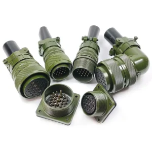
MIL-DTL-5015 Connector Construction
A typical circular connector consists of several interacting components.
Connector Shell
The shell is the primary mechanical housing.
Its functions include:
- protecting the insert
- supporting the coupling interface
- providing mounting features
- supporting rear accessories
- contributing to grounding or shielding when conductive
Common materials include:
- aluminum alloy
- stainless steel
- specialty materials for particular environments
Aluminum is widely used because it combines low weight with adequate mechanical performance.
Stainless steel may be selected for severe environments or higher mechanical durability.
Insulator and Insert
The insert positions and electrically isolates the contacts.
The insert arrangement determines:
- contact count
- contact size
- contact spacing
- contact pattern
- service rating
An insert arrangement is therefore not merely a contact count.
Two connectors with the same shell size can contain completely different contact patterns.
For a detailed explanation of arrangement codes, contact patterns, and mixed-contact layouts, see Connector Insert Arrangements.
Pin and Socket Contacts
A contact pair consists of:
- a pin contact
- a socket contact
The contact gender is independent of whether the connector body is called a plug or receptacle.
A plug can contain socket contacts.
A receptacle can contain pin contacts.
This is a common source of ordering mistakes.
For a more detailed explanation of contact gender, energized-side selection, and connector terminology, see Pin vs Socket Contacts.
For energized circuits, system designers commonly prefer to place power on recessed socket contacts where the applicable design and safety requirements permit.
Coupling Threads
The threaded coupling system creates mechanical engagement between the plug and receptacle.
The thread design varies by family.
The older MS3100 system and later MS3400/MS3450 systems may share mating interface compatibility in relevant configurations, but their rear accessory interfaces differ.
Key and Keyway Polarization
Keying helps orient the connector during mating.
The older 5015 interface uses relatively simple shell polarization compared with more modern multi-keyway connector standards.
Alternate insert rotations provide another method of preventing incorrect cross-mating between circuits using the same shell and insert arrangement.
Environmental Seals
Depending on the connector family and class, sealing components may include:
- interface seals
- shell seals
- rear wire grommets
- mounting gaskets
- backshell seals
The connector alone is only one part of the environmental system.
A poorly selected cable clamp or improperly sealed rear termination can compromise the complete assembly.
Accessory Interface
The rear accessory interface allows the installation of components such as:
- backshells
- cable clamps
- strain reliefs
- conduit adapters
- shielding hardware
Accessory compatibility must be checked against the exact connector family.
Cable Clamp and Backshell
A backshell can perform one or more functions:
- strain relief
- cable routing
- environmental sealing
- EMI shield termination
- mechanical protection
A basic cable clamp should not automatically be assumed to provide full environmental or EMI performance.
For more information about straight, angled, environmental, and EMI accessories, see MIL-Spec Connector Backshells.
The correct accessory should be selected for the actual cable and installation.
MIL-DTL-5015 Connector Types and Shell Styles
Wall-Mount Receptacles
A wall-mount receptacle is mounted to a panel or equipment enclosure.
The classic solder-contact designation is:
MS3100
In the crimp families, equivalent wall-mount styles include:
- MS3400
- MS3450
These are commonly used where a fixed equipment interface is required.
Cable-Connecting Receptacles
The classic solder family uses:
MS3101
This is a cable-mounted receptacle that mates with a plug.
In the later crimp families, corresponding cable-connecting or in-line receptacle styles include MS3401 and MS3451.
This terminology can confuse users because a cable-mounted component may casually be called a “plug,” while the formal connector designation is a receptacle.
Use the official part-number family rather than relying on appearance alone.
Box-Mount Receptacles
The traditional designation is:
MS3102
A box-mount receptacle is designed for mounting directly to equipment where the rear termination does not require the same accessory configuration as a cable-mounted connector.
Crimp-family equivalents include other dedicated box-mount configurations.
Straight Plugs
The classic solder-contact straight plug is:
MS3106
Crimp-family examples include:
- MS3406
- MS3456
Straight plugs are common on cable assemblies where the cable exits directly behind the connector.
Angle Plugs
The traditional 90-degree solder-contact plug is:
MS3108
The MS3400 family also includes angled plug variants.
Angle plugs can be useful where:
- rear clearance is limited
- cables must route along a panel
- strain from a straight cable exit would be undesirable
Hermetic Connectors
Hermetic connectors are used where ordinary environmental sealing is not sufficient.
Typical applications can include:
- pressure boundaries
- vacuum equipment
- sealed enclosures
- fluid isolation systems
Hermetic connectors may use glass-to-metal sealing technology and metal contact feedthrough structures.
Do not assume that an environmental connector is hermetic.
These are different performance concepts.
Filter Connectors
Filter connectors incorporate electrical filtering to help control:
- EMI
- RFI
- conducted interference
- unwanted high-frequency energy
Filtering may be achieved through:
- filtered contacts
- capacitive elements
- Pi-filter networks
The filter architecture should be matched to the actual electrical interference problem.
Contact Types and Sizes
Pin Contacts
Pin contacts provide the male electrical contact interface.
They can be used in either a plug or receptacle body, depending on the required configuration.
Socket Contacts
Socket contacts provide the female electrical contact interface.
In power systems, sockets are often preferred on the energized side because the live conductive interface can be more recessed.
The complete system design must still follow the applicable electrical safety requirements.
For a detailed comparison, see Pin vs Socket Contacts.
Solder Contacts
Solder contacts are permanently terminated by soldering the conductor to the contact.
Advantages include:
- established technology
- simple component architecture
- suitability for legacy repair
Disadvantages include:
- slower assembly
- operator dependence
- heat exposure
- more difficult contact replacement
Crimp Contacts
Crimp contacts are terminated using controlled mechanical compression.
A correct crimp requires:
- correct contact
- correct wire size
- specified tooling
- correct locator or positioner
- proper inspection
A high-quality crimp can provide repeatable electrical and mechanical performance without applying soldering heat to the termination.
Power Contacts
Large power contacts are a major reason to select the 5015 family.
Traditional MS3100 configurations can include contact sizes such as:
- 16
- 12
- 8
- 4
- 0
Not every insert arrangement uses every contact size.
Signal Contacts
Signal contacts are used for:
- control signals
- sensors
- instrumentation
- low-current circuits
Many insert arrangements combine multiple smaller contacts in one circular shell.
Thermocouple Contacts
Thermocouple contacts may be used in temperature measurement systems.
These applications require careful attention to:
- contact material
- extension wire material
- thermoelectric compatibility
A standard copper-alloy contact should not automatically be substituted into a thermocouple circuit.
Special-Purpose Contacts
Commercial derivatives may support additional contact technologies.
Examples can include:
- high-current contacts
- filtered contacts
- coaxial contacts
- specialized instrumentation contacts
Availability depends on the manufacturer and connector family.
Contact Selection Summary
Contact Type | Typical Purpose |
|---|---|
Signal | Control and instrumentation |
Power | Higher-current circuits |
Thermocouple | Temperature sensing |
Filtered | EMI/RFI control |
Specialty high-current | Enhanced power applications |
Important Rating Note
Never select a connector by a generic statement such as:
“MIL-DTL-5015 connectors carry X amperes.”
Actual current capability depends on:
- contact size
- contact material
- wire size
- number of energized contacts
- ambient temperature
- insert arrangement
- connector family
- manufacturer qualification
Shell Sizes and Insert Arrangements
What Is a Shell Size?
Shell size identifies the physical size of the connector interface.
In traditional circular connector nomenclature, the numerical shell size is related to the mating thread diameter.
For example, a shell size 24 corresponds approximately to a 1.5-inch mating thread basis:
24 ÷ 16 = 1.5
The traditional 5015 family includes standard sizes and short-shell designations such as:
- 8S
- 10S
- 10SL
- 12S
- 12
- 14S
- 14
- 16S
- 16
- 18
- 20
- 22
- 24
- 28
- 32
- 36
- 40
- 44
- 48
The letter S indicates a short-shell configuration in the traditional system.
For a broader explanation of how shell size affects mating dimensions, panel cutouts, and connector selection, see Circular Connector Shell Sizes.
What Is an Insert Arrangement?
The insert arrangement defines the contact pattern.
For example:
20-24
does not mean “shell size 20 with 24 contacts.”
It is a complete insert arrangement code.
The first portion usually relates to the shell family or shell size, while the second portion identifies the specific pattern.
A particular arrangement may contain:
- one contact
- several contacts
- many small contacts
- a mixture of contact sizes
For a full explanation of arrangement numbering and mixed-contact patterns, see Connector Insert Arrangements.
Always consult the correct insert chart.
Contact Quantity
Contact quantity varies greatly.
Depending on family and arrangement, a 5015-type connector can range from a single large power contact to a large group of smaller signal contacts.
The number of cavities alone does not determine electrical capability.
Contact Size
Two insert arrangements with the same number of contacts may use different contact sizes.
This changes:
- wire range
- current capability
- termination tooling
- application suitability
Pin vs Socket Configuration
After selecting an insert arrangement, the engineer must select contact gender.
Typical codes are:
- P = pin
- S = socket
This is separate from the plug or receptacle shell style.
Normal and Alternate Positions
Traditional 5015 part numbers can use:
- normal position
- W
- X
- Y
- Z
The alternate position rotates the insert relative to the normal arrangement.
Its purpose is to reduce the risk of mating connectors carrying incompatible circuits.
Not every rotation is available for every arrangement.
How to Read an Insert Arrangement
Consider:
20-24
The engineer should check:
- shell size
- total contact count
- individual contact sizes
- service rating
- pin or socket requirement
- alternate rotations
- availability in the selected connector family
An insert arrangement should never be selected from the code alone.
How to Read MIL-DTL-5015 Part Numbers
One of the most valuable skills when working with 5015 connectors is understanding the part number.
For a broader guide covering multiple connector standards, see How to Read MIL-Spec Connector Part Numbers.
Consider this example:
MS3106A20-24S
The number can be divided into:
MS3106 | A | 20-24 | S
Basic Connector Style: MS3106
MS3106 identifies the basic connector shell style.
In the traditional solder-contact family:
- MS3100 = wall-mount receptacle
- MS3101 = cable-connecting receptacle
- MS3102 = box-mount receptacle
- MS3106 = straight plug
- MS3108 = 90-degree plug
Therefore:
MS3106 = straight plug
Service Class: A
The next letter identifies the service class.
For this example:
A = service class A
Service-class meaning must be checked against the applicable family documentation.
It can affect:
- rear construction
- sealing
- cable support
- environmental performance
Do not assume that a service-class code means the same thing in an unrelated connector standard.
Shell Size and Insert Arrangement: 20-24
The complete code:
20-24
identifies the required shell and contact arrangement.
It should be treated as one complete insert designation.
The insert chart must be consulted to determine:
- number of contacts
- contact sizes
- service rating
Contact Gender: S
The final S means:
Socket contacts
A P would indicate pin contacts.
Therefore:
MS3106A20-24S
can be summarized as:
A traditional 5015-type straight plug, service class A, with insert arrangement 20-24 and socket contacts.
Alternate Position
An additional final letter may indicate an alternate insert position.
Example:
MS3106A20-24SW
Here:
- S = socket contacts
- W = alternate insert position W
Normal position is typically represented by the absence of an alternate-position suffix.
Do Not Apply One Part-Number Formula to Every 5015 Family
This is extremely important.
The part-number sequence for:
- MS3100
- MS3400
- MS3450
is not identical in every detail.
For example, a later crimp-family part number may include additional information for:
- class
- material
- shell size
- contact arrangement
- contact type
- polarization
Always decode the number using the catalog or specification sheet for the exact family.
MIL-DTL-5015 Service Classes
Service class is an important part of connector selection because two connectors with the same shell size and insert arrangement can have different rear construction or environmental performance.
Traditional MS3100 part numbers may include classes such as:
- A
- C
- E
- F
- R
Later AS50151-derived families can use additional class systems.
General-Duty Classes
General-duty configurations may be suitable where full environmental sealing is not required.
Typical considerations include:
- indoor equipment
- protected enclosures
- less severe contamination
- basic cable support
Environmental Classes
Environmental designs add features intended to improve resistance to:
- moisture
- dust
- fluids
- cable movement
The performance of the complete assembly also depends on:
- backshell
- cable diameter
- wire seals
- assembly quality
Firewall and High-Temperature Variants
Special classes can use:
- steel shells
- nickel finishes
- high-temperature construction
These configurations must be selected against the exact applicable specification.
Do not assume that an ordinary aluminum connector can be substituted for a firewall or high-temperature class.
Stainless Steel and Severe-Environment Options
Some crimp families include stainless steel options for severe environments.
Stainless steel may provide:
- increased mechanical durability
- corrosion resistance
- higher mass
- higher cost
Which Service Class Should You Select?
Ask:
- Is the connector indoors or outdoors?
- Will it be exposed to water?
- Is fluid exposure expected?
- Is a cable clamp required?
- Is a sealed rear grommet required?
- Is high temperature expected?
- Is stainless steel required?
- What does the drawing specify?
Never select a service class from appearance alone.
Materials and Finishes
The shell material and finish influence:
- corrosion resistance
- electrical conductivity
- EMI grounding
- galvanic compatibility
- temperature capability
- environmental compliance
- appearance
For a broader comparison of common circular connector surface treatments, see Connector Plating and Finishes.
Finish performance should always be checked for the exact connector series and manufacturer.
Aluminum Alloy Shells
Aluminum is widely used because it provides a useful balance of:
- low weight
- machinability
- adequate strength
- broad plating compatibility
Because bare aluminum can corrode, a protective surface treatment is normally required.
Stainless Steel Shells
Stainless steel is used where applications require:
- higher mechanical strength
- severe-environment resistance
- specialized high-temperature performance
The disadvantages are generally:
- greater weight
- higher cost
Olive Drab Cadmium
Olive drab cadmium is one of the most historically recognized finishes for rugged circular connectors.
Advantages
- excellent corrosion protection
- conductive surface
- good grounding characteristics
- compatibility with aluminum connector systems
- good lubricity
- proven history in rugged applications
- non-reflective olive-drab appearance
Disadvantages
- contains toxic cadmium
- subject to environmental restrictions
- requires controlled plating and waste treatment
- may be restricted in some markets
- increasingly replaced in new programs
Best For
- legacy drawings
- qualified existing systems
- harsh environments
- applications requiring conductive corrosion protection
Electroless Nickel
Electroless nickel is a conductive cadmium-free finish used where electrical continuity, wear resistance, and temperature capability are important.
Advantages
- good electrical conductivity
- low-resistance conductive surface
- strong EMI grounding potential
- good wear resistance
- uniform coating on complex shapes
- higher temperature capability than many cadmium systems
- cadmium-free
Disadvantages
- lower salt-spray performance on some aluminum systems
- less sacrificial protection after coating damage
- reflective appearance
- may be less suitable for prolonged severe marine exposure
Best For
- conductive shells
- EMI-sensitive applications
- higher-temperature systems
- equipment where a metallic appearance is acceptable
A key technical distinction is that electroless nickel functions mainly as a barrier coating.
When the coating remains intact, it protects the base material.
If aluminum is exposed through deep scratches or coating damage, the nickel does not protect the substrate in the same sacrificial manner as zinc-based finishes.
Black Zinc Nickel
Black zinc nickel is a cadmium-free conductive finish increasingly used as an alternative to traditional cadmium systems.
Advantages
- strong corrosion resistance
- conductive surface
- useful grounding performance
- non-reflective black appearance
- cadmium-free
- suitable for many RoHS-conscious applications
- available for harsh-environment connector systems
Disadvantages
- process quality depends on the plating system
- availability varies by manufacturer
- substitution may require approval
- not automatically interchangeable with every cadmium configuration
- exact compatibility must be verified
Best For
- cadmium replacement programs
- dark non-reflective equipment
- conductive shell requirements
- corrosion-resistant applications
Finish Comparison
Finish | Corrosion Protection | Conductivity | Main Advantage | Main Limitation |
|---|---|---|---|---|
Olive Drab Cadmium | High | Good | Proven harsh-environment performance | Toxicity and restrictions |
Electroless Nickel | Application-dependent | Excellent | Conductivity and temperature | Less sacrificial protection |
Black Zinc Nickel | High | Good | Cadmium-free corrosion protection | Substitution may require approval |
Important Finish Selection Rule
Do not choose a finish from color alone.
Check:
- finish code
- specification
- base material
- salt-spray requirement
- temperature
- mating finish
- backshell finish
- regulatory requirements
The connector and accessory should be evaluated as a complete material system.
Electrical Performance
Current-Carrying Capability
Current rating depends primarily on:
- contact size
- conductor size
- contact material
- temperature
- number of loaded contacts
- insert arrangement
- airflow
- connector design
A large size 0 power contact and a size 16 signal contact cannot be assigned the same current rating.
Always use the current derating data for the exact product.
Voltage Ratings
Voltage capability depends on:
- insert spacing
- dielectric system
- altitude
- contamination
- service rating
- environmental conditions
A connector should not be selected for voltage based only on shell size.
Contact Resistance
Low contact resistance helps reduce:
- voltage drop
- heating
- power loss
Contact resistance can be affected by:
- contact size
- plating
- contact wear
- contamination
- crimp quality
Insulation Resistance
Insulation resistance indicates the ability of the dielectric system to prevent unwanted leakage between circuits.
It may decrease because of:
- moisture
- contamination
- temperature
- damaged insulation
Dielectric Withstanding Voltage
Dielectric withstanding voltage evaluates whether the connector can tolerate a specified test voltage without electrical breakdown.
It is a qualification or verification parameter, not the same as normal operating voltage.
Shell-to-Shell Conductivity
For grounded and shielded systems, conductive shell finishes can help maintain electrical continuity across the mated connector.
Performance depends on:
- shell material
- finish
- mating interface
- contamination
- wear
- backshell bonding
Power vs Signal Circuits
The 5015 family is especially useful where a system needs:
- a small number of large power circuits
- medium-density control circuits
- mixed power and signal
For very high-density modern electronics, a smaller connector family such as MIL-DTL-38999 Connectors may be more efficient.
For miniature rectangular signal connections, MIL-DTL-83513 Micro-D Connectors may be more suitable.
Environmental Performance
Operating Temperature
Temperature capability depends on:
- service class
- shell material
- finish
- seals
- insert material
- contacts
Do not publish one temperature range for all 5015 connectors.
Moisture Resistance
Environmental configurations can use:
- wire seals
- interface seals
- gaskets
- sealing backshells
Correct cable diameter and assembly are essential.
Salt Spray and Corrosion
Corrosion resistance is strongly affected by finish.
Representative finish systems can range from relatively short salt-spray ratings for certain electroless nickel coatings to 500 hours or more for specific cadmium and zinc-nickel systems.
Therefore:
Finish selection matters as much as connector-family selection.
For additional guidance, see Connector Plating and Finishes.
Vibration and Mechanical Shock
Rugged circular construction makes the 5015 family suitable for equipment exposed to vibration and shock.
However, performance also depends on:
- coupling engagement
- cable support
- backshell
- wire strain
- connector mounting
A heavy unsupported cable can transfer damaging loads into the connector.
Dust and Contaminants
A mated environmental connector is only one part of the protection strategy.
Unused connectors should use protective covers when contamination presents a risk.
Chemical and Fluid Exposure
Potential exposures include:
- fuel
- oil
- hydraulic fluids
- cleaning chemicals
Seal and finish compatibility should be checked against the exact fluid.
Environmental vs Non-Environmental Connectors
Do not assume that all MIL-DTL-5015 connectors are waterproof.
The family includes multiple classes and construction types.
A more accurate statement is:
Environmental 5015 configurations are available, but sealing performance depends on the exact connector, class, accessory, cable, and assembly.
Advantages of MIL-DTL-5015 Connectors
The main advantages are:
Rugged Construction
Large circular shells provide strong mechanical protection.
Wide Contact Range
The family can accommodate signal contacts and large power contacts.
Power Capability
It is particularly useful for systems requiring larger conductors.
Extensive Insert Arrangements
Many historical contact patterns are available.
Long-Established Part Numbers
MS numbers are widely recognized by engineers and buyers.
Strong Replacement Availability
Multiple manufacturers support compatible interfaces and commercial equivalents.
Mixed Power and Signal
Certain arrangements allow different circuit functions in one connector.
Solder and Crimp Options
Users can support legacy solder systems or more maintainable crimp systems.
Limitations of MIL-DTL-5015 Connectors
A good engineering guide should also explain where the family is not ideal.
Larger Size
The connectors are generally larger than modern high-density aerospace connectors.
Higher Weight
Large shells and large contacts increase assembly weight.
Lower Contact Density
For dense electronic systems, MIL-DTL-38999 can provide more efficient packaging.
A detailed engineering comparison is available in MIL-DTL-38999 vs MIL-DTL-5015.
Slower Mating
Traditional threaded coupling requires more rotation than quick-disconnect bayonet systems.
Complex Legacy Variations
Different families use:
- solder contacts
- front-release contacts
- rear-release contacts
- different accessory interfaces
Part-Number Complexity
A small suffix change can alter:
- contact gender
- rotation
- service class
- finish
Not Ideal for Every Modern Application
A compact avionics unit may benefit more from MIL-DTL-38999 technology.
Miniature high-density signal electronics may instead use MIL-DTL-83513 Micro-D Connectors.
MIL-DTL-5015 Applications
Industrial Machinery
Typical uses include:
- motors
- machine tools
- automation equipment
- control cabinets
Heavy Equipment
Large contacts and rugged shells can suit:
- construction equipment
- mining systems
- material-handling equipment
Ground Vehicles
Applications may include:
- power distribution
- control systems
- electrical subsystems
Railway Systems
Potential uses include:
- rolling stock
- maintenance equipment
- power and control interfaces
Power Generation Equipment
The family can be used for:
- generators
- auxiliary systems
- control equipment
Marine Equipment
Properly selected materials and finishes may support marine or shipboard applications.
Severe salt exposure requires careful attention to:
- finish
- sealing
- accessory compatibility
Test and Measurement Systems
The large selection of contact arrangements can support:
- test equipment
- field instrumentation
- industrial measurement systems
Aerospace Ground Equipment
5015-type connectors are often practical where compact airborne packaging is less important than ruggedness and maintainability.
Legacy Equipment Replacement
This remains one of the most important applications.
Replacement projects should verify:
- exact part number
- mating connector
- contact layout
- alternate rotation
- accessory interface
- qualification requirement
Do not replace a legacy connector only by matching its diameter.
How to Select a MIL-DTL-5015 Connector
Step 1: Determine Power or Signal Requirements
Identify every circuit.
Record:
- voltage
- current
- signal type
- wire size
Step 2: Select Contact Size and Quantity
Determine:
- number of circuits
- required contact sizes
Do not choose contact size only from wire diameter.
Confirm the approved conductor range.
Step 3: Choose the Insert Arrangement
Find an arrangement that supports:
- correct contact quantity
- correct contact sizes
- required service rating
For detailed guidance, refer to Connector Insert Arrangements.
Step 4: Select the Shell Size
The insert arrangement normally determines the compatible shell size.
Do not increase or reduce shell size without checking arrangement availability.
For more information, see Circular Connector Shell Sizes.
Step 5: Choose Plug or Receptacle
Determine the mechanical interface:
- wall mount
- box mount
- cable connecting
- straight plug
- angle plug
Step 6: Select Solder or Crimp Termination
Choose between:
- MS3100 solder
- MS3400 front-release crimp
- MS3450 rear-release crimp
For existing systems, mating and drawing requirements may determine the choice.
Step 7: Select the Service Class
Evaluate:
- sealing
- cable support
- environment
- temperature
Step 8: Choose Shell Material and Finish
Compare:
- olive drab cadmium
- electroless nickel
- black zinc nickel
- stainless steel options
- other approved finishes
Additional finish comparisons are available in Connector Plating and Finishes.
Step 9: Confirm Environmental Requirements
Define:
- temperature
- moisture
- salt exposure
- vibration
- fluids
Step 10: Select Backshells and Accessories
Determine whether the assembly requires:
- cable clamp
- strain relief
- EMI backshell
- sealing backshell
- protective cover
See MIL-Spec Connector Backshells for common backshell types and selection considerations.
Step 11: Verify Mating Compatibility
Check both halves.
Confirm:
- family
- shell size
- insert arrangement
- contact gender
- alternate rotation
Step 12: Confirm Drawing and Qualification Requirements
Before ordering, verify:
- governing specification
- current SAE requirement
- exact MS number
- manufacturer approval
- QPL requirement where applicable
MIL-DTL-5015 Selection Checklist
Before ordering, confirm:
Item | Confirmed? |
|---|---|
Connector family | |
Shell style | |
Service class | |
Shell size | |
Insert arrangement | |
Contact gender | |
Alternate rotation | |
Contact termination | |
Material | |
Finish | |
Backshell | |
Qualification requirement |
MIL-DTL-5015 Accessories
Backshells
Backshells provide mechanical and environmental functions behind the connector.
For a complete explanation of available styles, see MIL-Spec Connector Backshells.
Cable Clamps
Cable clamps support the cable and reduce force on the terminations.
Strain Reliefs
A strain relief helps manage:
- bending
- pulling
- cable movement
Protective Covers
Protective covers can help protect unmated connectors from:
- dust
- debris
- moisture
- contact damage
Sealing Plugs
Unused contact cavities in applicable crimp connector systems may require sealing plugs to maintain environmental sealing.
Heat-Shrink Boots
Heat-shrink boots can provide:
- cable transition
- strain relief
- environmental protection
Adapters
Adapters may connect the connector to:
- conduit
- alternate backshell systems
- specialty cable hardware
Insertion and Extraction Tools
Crimp contact systems require correct tools for:
- contact installation
- contact removal
Do not use improvised tools that may damage the insert or retention system.
Important Accessory Compatibility Note
The MS3100 solder family and MS3400/MS3450 crimp families should not be assumed to use interchangeable rear accessories.
The crimp families can share mating interface features with MS3100/MS3106 while using a rear accessory interface that is not interchangeable with the older solder-family accessory interface.
This is one of the most important practical differences in the entire 5015 family.
MIL-DTL-5015 vs Other Connector Standards
MIL-DTL-5015 vs MIL-DTL-38999
MIL-DTL-5015 is generally larger and more power-oriented.
MIL-DTL-38999 is typically selected for more compact, higher-density electronic applications.
MIL-DTL-5015 | MIL-DTL-38999 |
|---|---|
Larger | More compact |
Lower density | Higher density |
Strong power capability | Optimized for dense electronics |
Traditional threaded coupling | Bayonet or tri-start systems |
Common in heavy equipment | Common in modern aerospace electronics |
Choose MIL-DTL-5015 When:
- large contacts are required
- equipment space is less restricted
- existing 5015 interfaces must be maintained
Choose MIL-DTL-38999 When:
- size and weight matter
- high contact density is required
- advanced EMI and environmental performance is required
For a complete side-by-side comparison, see MIL-DTL-38999 vs MIL-DTL-5015.
You can also review the complete MIL-DTL-38999 Connectors guide for series, shell styles, materials, contacts, and selection.
MIL-DTL-5015 vs MIL-DTL-26482
MIL-DTL-26482 is generally more compact and commonly uses bayonet coupling.
MIL-DTL-5015 | MIL-DTL-26482 |
|---|---|
Larger | More compact |
Threaded | Bayonet |
Strong for larger power contacts | Better for compact quick disconnect |
Lower to medium density | Medium density |
For a more detailed analysis of size, coupling, applications, and selection, see MIL-DTL-5015 vs MIL-DTL-26482.
Additional technical information is available in the complete MIL-DTL-26482 Connectors guide.
MIL-DTL-5015 vs MIL-DTL-22992
MIL-DTL-22992 is more strongly associated with heavy-duty power applications.
MIL-DTL-5015 provides broader flexibility for mixed:
- power
- control
- signal
MIL-DTL-22992 may be more suitable for dedicated high-power systems.
For a detailed comparison of power capability, size, applications, and environmental design, see MIL-DTL-5015 vs MIL-DTL-22992.
MIL-DTL-5015 vs Commercial Circular Connectors
Commercial connectors can provide:
- lower cost
- smaller size
- modern locking systems
However, they may lack:
- MS part-number compatibility
- established interchangeability
- required qualification documentation
The correct choice depends on whether the project is a new commercial design or a controlled replacement program.
Common MIL-DTL-5015 Selection Mistakes
Mistake 1: Selecting by Shell Size Alone
Shell size does not define the contact pattern.
Always check the insert arrangement.
Mistake 2: Ignoring the Insert Arrangement
Two same-size connectors may not mate electrically.
Review Connector Insert Arrangements before selecting by contact count alone.
Mistake 3: Confusing Plug Bodies with Pin Contacts
A plug can contain sockets.
A receptacle can contain pins.
For a detailed explanation, see Pin vs Socket Contacts.
Mistake 4: Assuming All 5015 Connectors Use the Same Termination
The family includes:
- solder
- front-release crimp
- rear-release crimp
Mistake 5: Ignoring Service Class
Service class can change the construction and environmental suitability.
Mistake 6: Assuming All Accessories Are Interchangeable
Rear accessory interfaces can differ between the solder and crimp families.
Mistake 7: Replacing Cadmium Without Approval
A cadmium-free finish may provide excellent performance, but an engineering substitution may still require:
- drawing revision
- customer approval
- qualification review
Review Connector Plating and Finishes when evaluating cadmium-free alternatives.
Mistake 8: Ignoring the Current SAE AS50151 Status
For new technical documentation, verify whether SAE AS50151 should be referenced instead of the canceled MIL-DTL-5015 document.
Frequently Asked Questions
What is a MIL-DTL-5015 connector?
A MIL-DTL-5015 connector is a rugged circular threaded electrical connector family originally standardized for power, control, and signal circuits.
The family includes solder, front-release crimp, and rear-release crimp contact systems.
Is MIL-DTL-5015 still active?
No.
MIL-DTL-5015H was canceled in 2009, and users were directed to SAE AS50151.
However, the term MIL-DTL-5015 remains widely used for products, drawings, and replacement procurement.
What replaced MIL-DTL-5015?
SAE AS50151 replaced MIL-DTL-5015.
What is the difference between MIL-C-5015 and MIL-DTL-5015?
MIL-C-5015 is the older designation.
MIL-DTL-5015 was the later military designation.
The connector family remained closely related, but exact revision and drawing requirements should always be checked.
What is the difference between MS3100 and MS3450 connectors?
MS3100 is the traditional solder-contact family.
MS3450 uses rear-release removable crimp contacts.
The MS3450 system is generally easier to service and better suited to modern crimp-based harness production.
What is the difference between MS3400 and MS3450?
Both use crimp contacts.
The key difference is contact removal:
- MS3400 = front release
- MS3450 = rear release
Are MIL-DTL-5015 connectors waterproof?
Some environmental configurations provide significant sealing, but not every 5015 connector is waterproof.
Performance depends on:
- family
- service class
- seals
- backshell
- cable
- assembly
Are MIL-DTL-5015 connectors suitable for high current?
Yes, many configurations are suitable for power circuits and large conductors.
However, current rating depends on the exact contact and operating conditions.
What is an insert arrangement?
An insert arrangement defines:
- contact pattern
- contact quantity
- contact sizes
- spacing
A code such as 20-24 identifies a particular arrangement, not simply a contact count.
For more information, see Connector Insert Arrangements.
How do I read a MIL-DTL-5015 part number?
For example:
MS3106A20-24S
can be separated into:
- MS3106 = straight plug
- A = service class
- 20-24 = insert arrangement
- S = socket contacts
Additional suffix letters can identify alternate insert positions.
For part-number structures across multiple MIL-Spec standards, see How to Read MIL-Spec Connector Part Numbers.
Can MIL-DTL-5015 connectors be replaced by MIL-DTL-38999?
Sometimes, but not as a direct universal substitution.
A conversion may require changes to:
- panel cutouts
- cable assemblies
- contact sizes
- accessories
- qualification
MIL-DTL-38999 is generally smaller and higher density.
See MIL-DTL-38999 vs MIL-DTL-5015 for a detailed comparison.
Are MS3100 and MS3400 connectors interchangeable?
Certain mating interfaces can be compatible, but that does not mean all parts and accessories are interchangeable.
The rear accessory interfaces can differ.
Which finish should I choose?
As a general guide:
- Olive Drab Cadmium: proven legacy harsh-environment performance
- Electroless Nickel: conductivity, wear, and higher temperature
- Black Zinc Nickel: cadmium-free corrosion-resistant alternative
The final choice should be based on the exact specification and environment.
For a broader comparison, see Connector Plating and Finishes.
Can black zinc nickel directly replace cadmium?
Not automatically.
Although black zinc nickel is widely used as a cadmium-free alternative, a legacy drawing may require formal engineering or customer approval before substitution.
Which connector family is best for new designs?
There is no universal answer.
Choose MS3100 when a legacy solder interface is required.
Choose a crimp family when production efficiency and maintainability are more important.
For highly compact and high-density equipment, MIL-DTL-38999 Connectors may be more appropriate.
For miniature rectangular signal connections, consider MIL-DTL-83513 Micro-D Connectors.
Related Guides
Related Connector Standards
- MIL-DTL-38999 Connectors
- MIL-DTL-26482 Connectors
- MIL-DTL-83513 Micro-D Connectors
Comparison Guides
- MIL-DTL-38999 vs MIL-DTL-5015
- MIL-DTL-5015 vs MIL-DTL-26482
- MIL-DTL-5015 vs MIL-DTL-22992
Technical Guides
- How to Read MIL-Spec Connector Part Numbers
- Circular Connector Shell Sizes
- Connector Insert Arrangements
- Pin vs Socket Contacts
- Connector Plating and Finishes
- MIL-Spec Connector Backshells
Conclusion
MIL-DTL-5015 remains one of the most recognizable circular connector families for rugged power, control, and signal applications.
Its main strengths are:
- rugged construction
- large contact capability
- extensive insert arrangements
- broad part-number recognition
- long-term replacement availability
- solder and crimp termination options
The family also requires careful selection.
Engineers and buyers must distinguish between:
- MS3100 solder connectors
- MS3400 front-release crimp connectors
- MS3450 rear-release crimp connectors
They must also verify:
- shell style
- service class
- insert arrangement
- contact gender
- alternate rotation
- material
- finish
- rear accessories
The most important standards point is that MIL-DTL-5015H has been canceled and replaced by SAE AS50151. Nevertheless, the name MIL-DTL-5015 continues to be widely used because of the enormous installed base of connectors, MS part numbers, engineering drawings, and replacement requirements.
For a new or replacement application, the safest approach is simple:
Select by the complete part number and technical requirement—not by appearance, shell size, or the “5015” name alone.
Contact Us
Category
- Industry News (3)
- Product News (14)
Office
Address
Jiangsu Province, China
Contact Information
Business Hours
Monday through Friday
8:30AM to 6:00PM