News
MIL-DTL-5015 Series: A Comprehensive Guide to Connectors and Specifications
Table of Contents
Toggle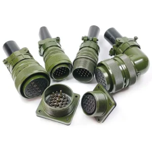
MIL-DTL-5015 connectors are heavy-duty circular electrical connectors used across military, aerospace, and industrial applications. These connectors handle both digital and analog signals as well as power distribution. You’ll find them in harsh environments where reliability matters most.
The MIL-DTL-5015 standard defines requirements for circular threaded electrical connectors with soldered or crimped contacts that meet strict military specifications. This standard evolved from the older MIL-C-5015 specification and is now also known as SAE-AS50151 in commercial applications. The connectors feature threaded or bayonet coupling styles that create secure connections even in demanding conditions.
You can choose from multiple shell sizes, contact layouts, and mounting options when selecting these connectors for your application. The series includes both solder and crimp contact types, with front or rear release options. Major manufacturers produce variants that maintain compatibility with the standard while offering improved features like better environmental sealing and easier installation.
Key Takeaways
- MIL-DTL-5015 connectors are military-grade circular connectors designed for harsh environments in defense, aerospace, and industrial applications
- These connectors offer multiple configurations including threaded or bayonet coupling, crimp or solder contacts, and various shell sizes to fit different needs
- The standard has evolved from MIL-C-5015 and is interchangeable with SAE-AS50151, ensuring broad compatibility across manufacturers and applications
Evolution of the MIL-DTL-5015 Standard
The MIL-DTL-5015 standard has undergone significant changes since its inception in the 1930s, evolving from the original AN9534 specification into today’s industry-recognized connector standard. The specification has been revised multiple times to improve performance requirements and eventually transitioned from a military standard to an industry technical standard under SAE-AS50151.
Historical Development and Origins
In the early 1930s, ITT Cannon received a contract from Douglas Aircraft Company to develop electrical circular connectors for the DC-1 aircraft. This work led to subsequent use on the DC-2 and DC-3 aircraft platforms. The collaboration resulted in the release of the AN9534 standard in 1939.
During the late 1930s, Cannon’s Type AN (Army-Navy) series established the foundation for modern circular connectors. The success of these early connectors prompted the military to formalize the specification. In 1949, the official MIL-C-5015 standard was established, replacing the earlier AN9534 designation.
The MIL-C-5015 standard set the requirements for heavy-duty circular electrical connectors with soldered or crimped contacts. These connectors were designed to handle both digital and analog signals as well as power distribution in demanding military applications.
Major Revisions and Superseding Standards
MIL-C-5015 underwent several important revisions throughout its history. The standard was updated in 1958, 1971, and 1976 to refine technical requirements and expand capabilities. The final revision under the MIL-C designation was MIL-C-5015G, released in March 1994.
In May 2000, MIL-C-5015G was superseded by MIL-DTL-5015H. This change represented a shift in military specification nomenclature. The new designation maintained the core requirements while updating testing procedures and performance criteria.
MIL-DTL-5015H was then superseded by SAE-AS50151 in December 2009. This transition followed the Department of Defense’s goal to reduce military standards in favor of industry technical standards. Despite the official change, manufacturers and users continue to refer to these connectors as MIL-DTL-5015 or MIL-C-5015 connectors.
Impact on Modern Industry
The standardization of these connectors created broad compatibility across multiple industries beyond military applications. You can now find MIL-DTL-5015 connectors in aerospace, oil and gas, telecommunications, mining, and rail applications. The widespread adoption made these connectors relatively inexpensive compared to other specialized connector types.
Many manufacturers including Amphenol and ITT Cannon produce connectors based on the MIL-DTL-5015 specification. These are available as off-the-shelf commercial products and as “mil-COTS” products for railway and military use. The standard defines 19 shell sizes with approximately 160 approved insert arrangements incorporating 1 to 85 contacts.
The transition to SAE-AS50151 brought the standard under the Society of Automotive Engineers’ control. This shift expanded the connector’s use in commercial applications while maintaining the rigorous performance requirements established by the original military specifications.

Key Features and Benefits
MIL-DTL-5015 connectors offer military-grade performance through robust construction, multiple configuration options, and reliable coupling systems. These features make them suitable for demanding applications where standard connectors would fail.
Ruggedness and Environmental Resistance
MIL-DTL-5015 connectors are built to handle extreme conditions. You get protection against vibration, shock, moisture, and temperature swings that would damage regular connectors.
The connectors include environmental sealing that keeps out water, dust, and contaminants. This sealing works through rubber grommets and gaskets at critical mating points. Hermetic connectors are available when you need complete airtight sealing for sensitive applications.
You can add backshells to your connector assembly for extra cable protection. These backshells provide strain relief that prevents damage from cable pulling or bending. The design includes large knurled surfaces that make handling easier, even when you wear gloves or work in tight spaces.
Versatility in Shell Sizes and Insert Arrangements
MIL-DTL-5015 connectors come in multiple shell sizes to match your space and power needs. Each shell size supports different contact counts and configurations.
Insert arrangements follow MIL-STD-1651 standards with 77 different options. You can choose inserts for power distribution, signal transmission, or mixed contact types. Common configurations include:
- Power contacts– Handle high current loads
- Signal contacts– Transmit data and control signals
- Mixed layouts– Combine power and signal in one connector
The standardized part numbering system tells you the shell size, insert arrangement, and contact type. This makes selecting mil-spec compatible connectors straightforward for replacements or new designs.
Threaded and Bayonet Coupling Mechanisms
Threaded coupling is the standard connection method for MIL-DTL-5015 connectors. You twist the coupling ring to secure the plug and receptacle together. This creates a tight, vibration-resistant connection.
The threads provide strong mechanical retention and maintain electrical contact under stress. Self-locking versions eliminate the need for safety wiring in critical applications. The single key and keyway polarization ensures you can only mate connectors in the correct orientation.
Some variants offer bayonet coupling for faster connections. You simply push and twist a quarter turn to lock. This saves time during repeated connect and disconnect cycles while maintaining secure attachment.
Connector Series and Variants
The MIL-DTL-5015 standard encompasses multiple connector series that differ primarily in their contact termination methods and release mechanisms. Each series offers distinct advantages for specific applications, from traditional solder contacts to modern crimp designs with front or rear release options.

Series I: Solder Contact Connectors
Series I represents the original MIL-DTL-5015 design, which uses solder cup contacts for wire termination. These connectors feature contact sizes ranging from #0 to #20 and can handle currents up to 225 amperes depending on the contact size. The MS3100 (plugs) and MS3106 (receptacles) are the most common designations you’ll encounter in this series.
You’ll find MS3106A, MS3108, MS3101, and MS3102 variants throughout military and industrial applications. The solder termination method provides reliable electrical connections but requires more assembly time and skill compared to crimp alternatives.
Series I connectors accommodate multiple contact arrangements in a single housing. You can mix power and signal contacts within the same connector shell. The robust threaded coupling mechanism ensures secure mating in high-vibration environments.
Series II: Front Release, Crimp Contact Connectors
MIL-DTL-5015 Series II introduces crimp contact technology with front-release mechanisms. This design allows you to insert and remove individual contacts from the front mating face of the connector after the backshell is installed.
Front release provides easier maintenance and field repairs. You can replace damaged contacts without disassembling the entire connector or removing it from your equipment. This feature reduces downtime during service operations.
The crimp termination method offers faster assembly than soldering. You need less specialized skill to achieve consistent, reliable connections. Series II maintains the same shell sizes and contact arrangements as Series I, giving you backward compatibility with existing systems.
Series III: Rear Release, Crimp Contact Connectors
Series III connectors use crimp contacts with rear-release extraction. Amphenol and other manufacturers developed this series as an improved alternative to the older solder-type connectors. You access the contacts from the wire side of the connector, which works better in certain installation configurations.
The rear-release design excels when the mating face of your connector is difficult to reach. You can service contacts without disconnecting mated pairs in some applications. This series bridges older connector standards with modern environmental and performance requirements.
Series III offers the same current ratings and environmental protection as other MIL-DTL-5015 variants. The crimp rear-release construction provides enhanced reliability in harsh conditions while simplifying assembly processes.
CA, Matrix, and Specialty Series
ITT Cannon’s CA series connectors derive from the MIL-C-5015 specification and expand the standard for commercial industrial and heavy vehicle applications. The CA series maintains compatibility with military specifications while offering cost-effective solutions for non-military uses.
Matrix catalog options provide additional configurations and materials. You can select from various shell finishes, including olive drab cadmium, black zinc-nickel, and electroless nickel plating. These choices let you match your specific environmental requirements.
MILNEC, Amphenol, and ITT Cannon manufacture specialty variants that meet or exceed MIL-DTL-5015 performance specifications. These products include enhanced sealing, extended temperature ranges, and unique contact arrangements. Some manufacturers offer hybrid designs that combine features from MIL-DTL-38999 Series III, such as faster-mating coupling mechanisms, while maintaining 5015 form factors.
Connector Configurations and Mounting Styles
MIL-DTL-5015 connectors come in several shell styles and mounting configurations to match different installation needs. Your choice depends on whether you need panel mounting, cable connections, or pass-through applications.

Wall Mount, Box Mount, and Bulkhead Feed-Thru
Wall mount receptacles (MS3450 type) feature a four-hole flange that lets you install the connector on either the front or back of a panel. You get mounting brackets and sealing screws with these receptacles for environmental protection. A mounting gasket helps seal the connection point.
Box mount receptacles (MS3452 type) also use a four-hole flange for panel mounting. The main difference is the low rear profile, which works well in tight spaces where you have limited room behind the panel. These receptacles don’t allow backshells because of the compact design.
Bulkhead feed-thru receptacles connect cable plugs from both sides of a panel. One side has socket contacts while the other side has pin contacts. The thru-bulkhead version (TM22) uses a mounting bracket and gasket for installation. The hermetic jam nut bulkhead feed-thru (TM27) creates an airtight seal and uses a single mounting hole, which makes it better for applications where you need to maintain vacuum pressure or keep out moisture.
Cable Plug and In-Line Receptacle Options
Cable plugs (MS3456 type) feature a wire sealing grommet that protects against harsh environments. You need strain relief backshells to protect the cable from tension at the termination point. These plugs mate with wall mount, box mount, jam nut, and cable mount receptacles.
In-line receptacles (MS3451 type) connect to cables rather than panels. They have a reduced flange that protects the coupling threads if the connector gets dropped or dragged across surfaces. You must use a strain relief backshell with these receptacles to prevent cable tension from damaging your wire terminations.
Both cable plugs and in-line receptacles work with the same mating connectors across different brands, including Amphenol, ITT Cannon, and Aero Electric products.
Dummy Receptacles and Sealing Accessories
Dummy receptacles protect unused ports on your equipment. They seal the opening and prevent debris, moisture, or contaminants from entering when you don’t have an active connection.
Sealing accessories include mounting gaskets, O-rings, and protective covers. Mounting gaskets create a seal between your receptacle and the panel surface. O-rings on jam nut receptacles (MS3454 type) maintain environmental integrity at the mounting location. Protective covers shield your contacts and coupling threads from damage when connectors are not in use.
Environmental backshells provide complete sealing at cable entry points. These backshells use cable glands that seal both the connector interface and the cable exit point. You can choose straight, 45-degree, or 90-degree angles based on your cable routing needs.
Self-Locking and Quick Disconnect Plugs
Self-locking plugs give you extra coupling security in high-vibration environments. The self-locking clutch creates both a tactile feel and an audible click when you properly connect the plug. This confirms your connection is secure and won’t vibrate loose during operation.
The self-locking design works with standard MIL-DTL-5015 receptacles without requiring special mating connectors. You can use these plugs anywhere you need added protection against accidental disconnection.
Standard threaded coupling plugs use a traditional coupling ring that you turn to secure the connection. These straight plugs work for applications where vibration is not a primary concern. The threaded design still provides a reliable connection that meets military specifications for performance and durability.
Contact Types and Insert Arrangements
MIL-DTL-5015 connectors use different contact types and insert arrangements to meet various electrical and mechanical requirements. The contact retention system and insert configuration determine how many contacts fit in each shell size and how they connect to wires.
Solder and Crimp Contact Systems
You can choose between solder contacts and crimp contacts for your MIL-DTL-5015 connectors. Crimp contacts are more common because they create reliable connections faster and require less skill to install properly. These contacts use a crimping tool to compress the contact barrel around the wire, creating a gas-tight connection.
Solder contacts require you to heat the contact and apply solder to bond the wire. This method takes more time and skill but works well for certain applications. Most modern MIL-DTL-5015 connectors use crimp contacts per MIL-C-5015G specifications because they perform consistently and allow for faster assembly.
The rear release contact retention system lets you remove individual contacts from the back of the connector without disassembling the entire unit. This feature makes repairs and modifications easier in the field.
Socket and Pin Contacts
Insert arrangements define how socket and pin contacts are positioned within the connector shell. Each arrangement has a specific number of contacts in sizes 16, 16S, 12, 8, 4, and 0 gauge. The socket contact accepts the pin contact from the mating connector to complete the electrical circuit.
You must match the insert arrangement between mating connectors for proper connection. Over 150 different insert arrangements are available across 14 shell sizes (8 to 40). The arrangement code tells you exactly how many contacts of each size fit in a particular shell.
RADSOK contacts use a unique design with multiple contact points that maintain reliable electrical connection even in high-vibration environments. These contacts provide better performance than standard pin and socket designs in demanding applications.
High Power and Specialty Contacts
High power contacts in sizes 4 and 0 gauge carry significantly more current than standard 16 gauge contacts. These larger contacts handle power transmission requirements while smaller contacts in the same connector manage signal and control circuits. You can mix different contact sizes within a single insert arrangement based on your application needs.
Contact arrangements also include specialty options for coaxial cables, fiber optics, and thermocouple wires. The insert arrangement drawings show the exact position and rotation of each contact within the shell. You need to verify wire gauge compatibility with your chosen contact size before selecting an insert arrangement.
Accessories, Options, and Customization
MIL-DTL-5015 connectors work with multiple accessories that protect connections and adapt them to specific needs. Strain relief components, environmental sealing solutions, and mounting hardware let you configure these connectors for demanding applications.
Strain Relief Clamps and Backshells
Backshells attach to the rear of your connector to provide cable strain relief and protect the wire terminations from damage. These accessories clamp onto the cable jacket and transfer mechanical stress away from the electrical contacts. You can choose from straight, 45-degree, or 90-degree angled backshells depending on your cable routing needs.
Most backshells use a strain relief clamp design with two or more screws that tighten around the cable. The clamp distributes pulling forces across the cable jacket instead of letting stress reach the wire connections inside the connector.
Backshells come in aluminum or stainless steel materials. You need to match the backshell thread size to your specific connector shell size. Some designs include cable entry grommets that seal around individual or bundled cables.
Environmental and Hermetic Sealing Solutions
Environmental sealing accessories protect your connections from moisture, dust, chemicals, and pressure changes. Standard gaskets and O-rings fit between mating connector halves to create basic environmental seals. These work well for applications exposed to splash or light contamination.
Hermetic connectors use glass-to-metal seals that create an airtight barrier. You need these when your application requires vacuum pressure maintenance or complete protection from caustic chemicals and moisture ingress. Glass-sealed pins pass through the connector shell without any path for fluid or gas penetration.
Potting backshells let you fill the rear of the connector with epoxy or other compounds. This creates a permanent environmental seal around the wire entry points.
Keyway, Polarization, and Mounting Accessories
Keyways and polarization features prevent incorrect mating between connectors. Your connector includes a keyway slot and matching key that only allow insertion in one orientation. This stops you from accidentally connecting mismatched circuits or reversing polarity.
Mounting brackets and flanges let you secure connectors to panels, bulkheads, or equipment housings. Receptacle connectors often include mounting threads or bolt holes for rigid installation. You install a mounting gasket between the connector flange and panel surface to maintain environmental sealing at the mounting interface.
Dust caps and protective covers keep unmated connectors clean during storage and transport. Dummy receptacles provide the same mounting footprint as active connectors for prototype or backup positions.
Frequently Asked Questions
MIL-DTL-5015 connectors offer multiple configuration choices that affect installation, performance, and longevity. Understanding these options helps you match connector specifications to your application’s electrical, mechanical, and environmental demands.
What are the main differences between the available shell styles and mounting options for these circular connectors?
MIL-DTL-5015 connectors come in several shell styles designed for different mounting needs. Box-mount receptacles attach to panels or enclosures with threaded inserts or mounting holes. Jam-nut receptacles use a single nut to secure the connector through a panel opening.
Straight plugs connect directly in line with the mating receptacle. Right-angle plugs redirect the cable 90 degrees from the connector face, which saves space in tight installations.
Wall-mount receptacles provide flanged attachment points for permanent installations. Each style maintains the same contact arrangements and electrical performance while offering different mechanical mounting solutions.
How do I select the correct insert arrangement and contact size for my application requirements?
Insert arrangements determine how many contacts fit within the connector shell and their layout pattern. You’ll find arrangements labeled with numbers and letters that indicate contact quantity and configuration. Common arrangements range from 2 to 128 contacts depending on shell size.
Contact size directly relates to current-carrying capacity. Size 16 contacts handle moderate current loads and are widely used for signal and low-power applications. Size 12 contacts support higher currents for power distribution.
You need to calculate your total current requirements and signal count before selecting an insert. Leave some capacity margin for heat dissipation and future expansion needs.
Which coupling mechanisms are available, and how do they affect vibration resistance and serviceability?
Threaded coupling provides the most secure connection and highest vibration resistance. You turn the coupling ring multiple rotations to fully engage the threads, creating a tight mechanical lock. This coupling style works best in high-vibration environments like vehicles and machinery.
Bayonet coupling uses pins and slots for quick connection and disconnection. You insert the connector and rotate it a quarter turn to lock it in place. This mechanism speeds up assembly and maintenance but offers less vibration resistance than threaded coupling.
Push-pull coupling enables the fastest mating and unmating with one hand. This style suits applications where you frequently connect and disconnect, though it provides the lowest vibration resistance of the three options.
What environmental sealing and operating temperature ranges should be expected for these connector families?
MIL-DTL-5015 connectors typically operate from -65°F to +200°F (-54°C to +93°C) in standard configurations. Some variants with special materials extend this range to +250°F (+121°C) for high-temperature applications.
Environmental sealing depends on proper gasket installation and mating engagement. When correctly assembled, these connectors achieve IP67 or better ingress protection ratings. The rear accessory threads accept cable glands or backshells that maintain sealing integrity at the cable entry point.
You must use compatible gasket materials and ensure full thread engagement to maintain environmental protection. Salt spray, humidity, and fluid immersion resistance vary based on shell plating and gasket selection.
How are current ratings, voltage ratings, and wire gauge ranges determined for the contacts used in these connectors?
Contact current ratings depend on contact size, plating, and ambient temperature. Size 16 contacts typically handle 7.5 to 13 amps per contact, while size 12 contacts support 20 to 23 amps. These ratings assume standard copper alloy contacts with proper crimping.
Voltage ratings relate to contact spacing and insulation materials. Most MIL-DTL-5015 connectors handle 250 to 500 volts AC/DC between adjacent contacts. Higher voltages require larger shell sizes with greater contact separation.
Wire gauge compatibility matches contact size. Size 16 contacts accept 16 to 20 AWG wire. Size 12 contacts work with 12 to 16 AWG wire. You should verify crimp tool specifications and contact manufacturer datasheets for exact wire ranges.
What plating and material options are commonly chosen to improve corrosion resistance and mating durability?
Cadmium plating over aluminum shells provides good corrosion resistance for general military applications. Nickel plating offers better protection in marine and industrial environments where salt exposure occurs. Olive drab chromate finishes serve applications requiring lower visibility.
Contact plating significantly affects performance and longevity. Gold plating on contacts ensures reliable low-resistance connections for signals and prevents oxidation during storage. Silver plating works well for power contacts due to excellent conductivity.
Tin plating presents a cost-effective option for commercial applications with less demanding environmental exposure. Stainless steel shells eliminate corrosion concerns entirely but add weight and cost compared to plated aluminum.
Contact Us
Category
- Industry News (3)
- Product News (14)
Office
Address
Jiangsu Province, China
Contact Information
Business Hours
Monday through Friday
8:30AM to 6:00PM