News
MIL-DTL-38999 Series III Backshell: Complete Guide & Applications
Table of Contents
Toggle
MIL-DTL-38999 Series III backshells are protective components that attach to military-spec circular connectors to provide strain relief, EMI shielding, and environmental protection for cable assemblies. These backshells connect to D38999 Series III connectors and create a secure interface between the connector body and the cable. You’ll find them in aerospace, defense, and industrial applications where reliable electrical connections matter.
MIL-DTL-38999 Series III backshells meet strict military performance standards while offering compatibility with multiple connector configurations, making them essential for protecting your critical cable assemblies. The backshells come in straight and 90-degree angle options to fit different installation needs. They work with both Series III and Series IV connector types.
When you select the right backshell for your connector, you get proper cable management and mechanical protection for your wiring system. The backshells use materials and designs that resist harsh environments including moisture, vibration, and electromagnetic interference. Understanding how these components work helps you build more reliable electrical systems.
Key Takeaways
- MIL-DTL-38999 Series III backshells provide strain relief, EMI shielding, and environmental protection for military-spec circular connectors
- These backshells are compatible with D38999 Series III and IV connectors in both straight and 90-degree configurations
- Proper backshell selection and installation ensures cable assembly reliability in aerospace, defense, and industrial applications
Core Features and Performance Standards
MIL-DTL-38999 Series III backshells deliver critical protection through advanced shielding, environmental sealing, and material selection. These features ensure reliable cable termination in aerospace, defense, and industrial systems where connector integrity directly affects mission success.
How to Order MIL-DTL-38999 Series III Backshells
Ordering the correct MIL-DTL-38999 Series III backshell isn’t just about picking a connector accessory off a shelf — it requires matching the shell size, backshell style (straight, 45°, or 90°), termination type, cable entry diameter, and finish to your specific connector and cable assembly. Get any of these wrong and you risk a poor strain relief fit, EMI shielding issues, or a part that simply won’t mate.
This guide walks through how to read a MIL-DTL-38999 Series III backshell part number, the key ordering codes you’ll need (shell size, angle, coupling type, material/finish, and cable clamp range), and practical tips to make sure you order the right part the first time.
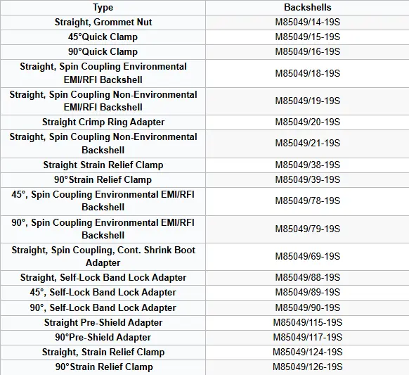
High-Density Shielding and 360° Termination
The 360° shield termination in D38999 Series III backshells provides complete electromagnetic interference protection around the cable junction. This design creates a continuous conductive path between the cable shield and the connector shell.
You achieve maximum EMI suppression when the backshell maintains metal-to-metal contact across the entire circumference. The termination method prevents signal degradation in high-frequency applications and radio communication systems. MIL-DTL-38999 backshells use spring fingers, conductive gaskets, or clamping bands to secure the shield without gaps.
Shield termination methods include:
- Band clamps– Apply uniform pressure around shielded cables
- Compression rings– Create direct contact with braided shields
- Integrated fingers– Maintain spring tension for long-term contact
This full-circle approach blocks external interference while containing internal emissions. Your system maintains signal integrity even in electrically noisy environments like avionics bays or radar installations.
Environmental Sealing and Fluid Resistance
Environmental sealing in MIL-DTL-38999 Series III backshells protects cable terminations from moisture, dust, hydraulic fluid, and fuel. The backshell uses O-rings and gaskets at both the connector interface and cable exit points.
When properly installed, these seals meet IP67 or higher ratings for water and particulate ingress. You can operate sealed assemblies in temperatures ranging from -65°F to +392°F depending on material selection. The dual-seal design prevents contamination from reaching the contact area where electrical connections occur.
Backshells resist exposure to jet fuel, hydraulic oil, cleaning solvents, and salt spray. This fluid resistance makes them suitable for aircraft fuel systems, shipboard electronics, and ground vehicle applications. Thread-locking compounds and heat-shrink boots add secondary protection layers.
Materials and Plating Options
Composite backshells offer significant weight reduction compared to aluminum or stainless steel versions while maintaining mechanical strength. You can select materials based on application requirements for corrosion resistance, weight limits, and electrical conductivity.
Common material and finish combinations:
|
Material |
Plating/Finish |
Primary Benefit |
|---|---|---|
|
Aluminum |
Olive drab cadmium |
Standard military use |
|
Aluminum |
Electroless nickel |
Enhanced corrosion resistance |
|
Stainless steel |
Passivated |
Marine environments |
|
Composite |
Conductive coating |
Maximum weight savings |
Cadmium plating provides proven corrosion protection but faces environmental restrictions in some regions. Electroless nickel serves as a compliant alternative with similar performance. Stainless steel backshells handle extreme salt spray and chemical exposure without degradation.
Major Types and Configurations
MIL-DTL-38999 Series III backshells come in several distinct types designed for specific installation needs and environmental protection levels. Each configuration serves different functions, from basic cable strain relief to advanced EMI shielding and environmental sealing.
Standard Backshells and Adapter Styles
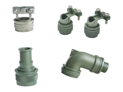
Standard backshells attach to your MIL-DTL-38999 Series III connectors through accessory threads and provide basic cable strain relief and mechanical protection. These backshells typically feature straight or 90-degree cable exits, allowing you to route cables according to your space constraints.
You can choose between metal and composite materials based on your weight requirements. Metal backshells offer superior strength and grounding, while composite backshells reduce overall system weight by up to 25% compared to metal alternatives.
The most common adapter styles include:
- Straight backshells– Direct cable exit for standard routing
- 45-degree adapters– Angled exit for space-limited applications
- 90-degree backshells– Right-angle cable routing for tight installations
- Cable clamp adapters– Adjustable strain relief for various cable diameters
These adapters maintain compatibility with all standard Series III connector shell sizes from 8 through 25. You select your backshell size to match your connector shell size and cable diameter.
Environmental and EMI Backshells
Environmental backshells provide sealed cable entry points that maintain the IP67 or IP68 rating of your Series III connector assembly. These backshells use internal sealing grommets or potting compounds to prevent moisture, dust, and contaminant ingress at the cable entry point.
EMI backshells offer electromagnetic interference shielding through 360-degree contact with your cable shield. You achieve shielding effectiveness of 65dB minimum at 10 GHz when properly installed with shielded cables. The backshell creates a continuous ground path from the connector shell through the cable shield to your equipment chassis.
Many environmental backshells combine both sealing and EMI protection. These dual-function backshells feature internal grommets that compress around your cable jacket while maintaining contact with the cable shield braid.
Shrink Boot Adapters and Shorting Cap Backshells
Shrink boot adapters provide a lightweight alternative to traditional backshells when you need basic environmental sealing without EMI shielding. You install a heat-shrink boot over the adapter body after cable attachment, creating a sealed interface that protects against moisture and contamination.
These adapters weigh significantly less than metal backshells and cost less to procure. You typically use them in aircraft and aerospace applications where weight reduction is critical.
Shorting cap backshells serve specialized functions in test and maintenance operations. These backshells include internal circuitry that shorts specific contact positions when installed, allowing you to safely test or store connector assemblies. You remove the shorting cap backshell before making the final connection to your mating receptacle.
Cable Management and Mechanical Protection
Backshells for MIL-DTL-38999 Series III connectors handle two critical functions: securing cables against mechanical stress and properly terminating electromagnetic shields. These components prevent premature connector failure by distributing tension loads away from contact terminations and maintaining signal integrity through continuous shield paths.
Strain Relief Backshells and Cable Clamps
Strain relief prevents cable movement from transferring force directly to the crimp contacts inside your connector. Without proper strain relief, vibration and pulling forces cause contact degradation and eventual circuit failure.
MIL-DTL-38999 Series III backshells use either band-style or grommet-style cable clamps. Band-style clamps wrap around the cable jacket with a metal band tightened by screws, providing adjustable grip force for various cable diameters. Grommet-style designs compress a rubber or elastomeric insert around the cable when you thread the backshell together.
Common Strain Relief Configurations:
- 45-degree and 90-degree backshells: Route cables at angles to reduce bending stress at the connector interface
- Straight backshells: Provide inline cable exit for applications with limited radial space
- Multiple cable entry backshells: Accommodate two or more cables entering from different positions
You should select backshell size based on your cable outer diameter range. The backshell must compress the cable firmly without crushing the jacket or internal conductors. Most manufacturers specify minimum and maximum cable diameters for each backshell part number.
Shield Termination Hardware and Techniques
Shield termination maintains the electromagnetic shielding effectiveness of your cable system by creating a 360-degree connection between cable shield and connector shell. Poor shield termination creates gaps that allow EMI to enter or exit your system.
The standard technique uses a shield termination ferrule or adapter that clamps onto the exposed cable shield braid. You strip back the cable jacket to expose the shield, fold it back over the ferrule, and secure it with the backshell compression mechanism. This creates metal-to-metal contact between shield, ferrule, and connector shell.
Shield Termination Best Practices:
- Maintain shield coverage over at least 75% of the cable circumference during installation
- Clean oxidation from shield braids before termination to ensure low-resistance contact
- Use conductive grease on shield contact surfaces in corrosive environments
- Verify continuity between cable shield and connector shell after assembly
Some backshells include integrated shield termination hardware that eliminates separate ferrule components. These designs simplify installation while maintaining proper shield grounding through the backshell body.
Connector Accessories and Protective Components
MIL-DTL-38999 Series III systems require specific accessories to maintain connector integrity when not in use. Dummy receptacles provide temporary connection points during storage and testing, while protective covers shield exposed connector faces from environmental damage.
Dummy Receptacles and Dummy Receptacle Applications
Dummy receptacles serve as placeholder components in MIL-DTL-38999 Series III systems. These accessories come in two main types: D38999/22 for threaded coupling connections and D38999/50 for bayonet coupling configurations.
You use dummy stowage receptacles when you need to store unused cable assemblies or when testing individual components. The receptacle accepts the plug end of your cable assembly and protects it from dust, moisture, and physical damage. This is particularly important in military and aerospace applications where cables may remain disconnected for extended periods.
The threaded coupling version (D38999/22) provides a secure attachment through the standard triple-start thread pattern. The bayonet coupling option (D38999/50) offers quick-connect functionality with a single turn. Both types maintain the environmental sealing properties that make Series III connectors reliable in harsh conditions.
Protective Covers and Caps
You need protective covers to shield both plug and receptacle connector faces when they’re disconnected. The MIL-DTL-38999 specification includes several protective cover options: MS27501 and MS27502 covers, MS27510 and MS27511 covers, and D38999/32 and D38999/33 covers designed specifically for Series III threaded connectors.
These protective caps prevent contamination, corrosion, and contact damage during storage, shipping, and maintenance. The covers come in composite or metal materials depending on your application requirements. You should select covers based on the expected environmental conditions and duration of protection needed.
Metal covers provide superior durability for long-term storage, while composite options offer lighter weight for applications where mass is a concern. Both types create a barrier against moisture, dirt, and other contaminants that could compromise your connector’s performance.
Compatibility with D38999 Connectors and Series
Backshells designed for MIL-DTL-38999 Series III connectors work with specific connector types and configurations. Understanding which backshells match your connector setup helps you avoid compatibility issues and ensures proper strain relief and environmental sealing.
MIL-DTL-38999 Series III Integration
MIL-DTL-38999 Series III backshells mate directly with all D38999 Series III connector configurations. The backshells attach to the accessory threads on the connector body. These threads provide environmental sealing and mechanical protection for your cable connections.
You can use Series III backshells with multiple connector styles. These include straight plugs like the D38999/26, jam-nut receptacles, and wall mount receptacles. The backshells accommodate various shell sizes from A through N.
The triple-start threads on Series III connectors allow quick attachment of backshells. You need only one turn to engage the self-locking connection. This design prevents loosening in high-vibration environments where your equipment operates.
Cross-Compatibility Across MIL-Spec Series
Series III backshells also work with MIL-DTL-26482 circular connectors due to similar thread patterns. Some manufacturers design backshells labeled as “Series A3” or similar that fit both MIL-DTL-38999 Series III and Series IV connectors. You should verify thread specifications before ordering.
Series I and Series II connectors use different accessory thread specifications. Backshells made for Series III will not properly mate with these earlier series. You must match your backshell to your specific connector series.
When selecting backshells, check the manufacturer’s compatibility charts. These charts list which connector slash sheets work with each backshell design. Common compatible slash sheets include D38999/20, D38999/24, and D38999/26 for environmental connectors.
Selection, Installation, and Best Practices
Proper backshell selection and installation directly affects connector performance in military and aerospace applications. The right combination of environmental sealing and shield termination keeps your system reliable in harsh conditions.
Choosing the Right Backshell and Adapter
You need to match your backshell to your specific cable type and operating environment. Series III backshells come in several configurations including strain relief, EMI/RFI shielding, and environmental sealing options.
Start by identifying your cable diameter and whether you need straight, 45-degree, or 90-degree cable exit angles. The shell size of your MIL-DTL-38999 Series III connector determines which backshell adapter you can use. Check the interface dimensions in your connector specifications to ensure proper fit.
Key backshell types include:
- Strain relief backshells– Protect wire-to-contact connections from mechanical stress
- EMI/RFI backshells– Provide electromagnetic shielding with band clamps or composite shield socks
- Environmental backshells– Offer cable sealing for moisture and contaminant protection
- Combination designs– Integrate multiple functions like swing-arm strain relief with EMI shielding
Rotatable coupling backshells with self-locking threads prevent loosening from vibration. Composite backshells reduce weight compared to metal options while maintaining performance in the -65 to +200°C operating range.
Maintaining Environmental and EMI Performance
Your shield termination method affects both EMI protection and environmental sealing. Band clamps create 360-degree contact between cable shields and backshells, which blocks electromagnetic interference more effectively than partial coverage.
Use the proper crimp tool specifications when attaching contacts before backshell installation. The M22520 series tools provide consistent crimp quality for Series III contacts. Install O-rings or sealing gaskets between the connector and backshell adapter to maintain environmental ratings.
Apply heat shrink boots over completed assemblies for additional moisture protection and strain relief. Make sure you select boots sized for your specific shell configuration. Tighten band clamps to manufacturer torque specifications to avoid damaging cable shields while ensuring proper electrical contact.
Inspect threaded coupling rings for damage before assembly. Cross-threading or debris can compromise both mechanical retention and environmental seals.
Frequently Asked Questions
Selecting the right backshell for MIL-DTL-38999 Series III connectors requires understanding shell sizes, thread types, EMI requirements, and compatibility standards. You need to match backshell dimensions to your connector specifications and verify performance requirements before installation.
How do I choose the correct backshell size and thread for my connector shell size and insert arrangement?
You need to match the backshell shell size to your connector’s shell size number. Each shell size has a corresponding thread specification that you must verify before ordering.
The insert arrangement does not typically affect backshell selection. Your primary concern is the outer shell diameter and thread type. Most Series III backshells use standard thread configurations that correspond directly to numbered shell sizes.
You should check the connector’s thread class and ensure the backshell matches exactly. Mismatched threads can cause poor sealing and connection failures.
What are the key specification requirements to verify for Series III backshell compatibility and performance?
You must verify that your backshell meets MIL-DTL-38999 qualification standards. Series III connectors require backshells that pass mechanical endurance and environmental testing as specified in the standard.
The operating temperature range should be -65 to +200°C for full specification compliance. You need to confirm that your backshell materials can handle this range.
Check the EMI/RFI shielding effectiveness if your application requires electromagnetic protection. The backshell must maintain the connector’s environmental resistance ratings for moisture, salt spray, and vibration.
Which backshell types are available (straight, angled, EMI/RFI, strain relief), and when should each be used?
Straight backshells work best when you have adequate space behind the connector and cables run in line with the connector axis. These are the simplest and most common type.
Angled backshells let you route cables at 45, 90, or other angles when space constraints prevent straight cable runs. You should use these in tight installations or when cables need to exit parallel to a mounting surface.
EMI/RFI backshells provide electromagnetic shielding through metal construction and proper grounding. Use these when your system requires protection from electromagnetic interference.
Strain relief backshells protect cable terminations from pull forces and vibration. You need these in applications where cables experience movement or mechanical stress.
How do I select the right backshell adapter and accessory threads for transitions to conduit, heat shrink, or braided shield termination?
Your adapter selection depends on your cable termination method and environmental sealing needs. Each transition type requires specific thread configurations and sealing mechanisms.
For conduit connections, you need backshells with NPT or metric conduit threads that match your cable protection system. These provide rigid cable routing and additional mechanical protection.
Heat shrink boots require backshells with smooth exit areas designed to accommodate shrink tubing. You should verify the exit diameter matches your heat shrink size requirements.
Braided shield terminations need backshells with built-in shield termination features or compatible accessories. The shield must make continuous electrical contact with the backshell for proper EMI protection.
Where can I find reliable technical drawings, catalogs, or PDFs for dimensions and ordering information?
Major manufacturers like Amphenol Aerospace, Glenair, and TE Connectivity provide detailed selection guides and technical documentation. You can access these resources through their websites or by requesting printed catalogs.
The selection guides include shell size charts, thread specifications, and dimensional drawings. You should reference these documents to verify exact measurements before ordering.
Distributors like Mouser Electronics maintain online catalogs with datasheets and specifications. These platforms let you compare products and access manufacturer documentation in one location.
What are the main differences between Series III and Series IV connectors and their backshell/intermate options?
Series III and Series IV connectors have different coupling mechanisms and shell configurations. Series III uses a bayonet coupling while Series IV uses a threaded coupling system.
The backshells for each series are not interchangeable due to different shell geometries and thread patterns. You must order backshells specifically designed for your series type.
Series IV connectors generally offer higher density contact arrangements. Your backshell selection must account for these differences in physical dimensions and mating characteristics.
Related Guides
Related Connector Standards
- MIL-DTL-38999 Connectors
- MIL-DTL-26482 Connectors
- MIL-DTL-83513 Micro-D Connectors
Comparison Guides
- MIL-DTL-38999 vs MIL-DTL-5015
- MIL-DTL-5015 vs MIL-DTL-26482
- MIL-DTL-5015 vs MIL-DTL-22992
Technical Guides
- How to Read MIL-Spec Connector Part Numbers
- Circular Connector Shell Sizes
- Connector Insert Arrangements
- Pin vs Socket Contacts
- Connector Plating and Finishes
- MIL-Spec Connector Backshells
Contact Us
Category
- Industry News (3)
- Product News (14)
Office
Address
Jiangsu Province, China
Contact Information
Business Hours
Monday through Friday
8:30AM to 6:00PM