News
MIL-DTL-83513: Ultimate Guide to Micro-D Connectors and Specifications
Table of Contents
Toggle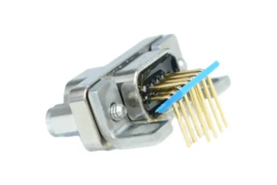
What Is MIL-DTL-83513?
MIL-DTL-83513 is a military specification that covers microminiature rectangular electrical connectors with polarized shells. These connectors are commonly known as Micro-D connectors and are designed for applications where space and weight are limited. You’ll find them in aerospace, defense, and industrial systems that need reliable connections in harsh environments.
MIL-DTL-83513 connectors provide high-density contact arrangements in compact packages that can withstand extreme temperatures, vibration, shock, and moisture. The specification includes eight different shell sizes that can hold anywhere from 9 to 100 contacts. These connectors meet strict military standards for performance and durability, making them a trusted choice when failure is not an option.
If you’re working on a project that requires small, lightweight connectors without sacrificing reliability, understanding MIL-DTL-83513 specifications will help you select the right solution. This guide covers everything you need to know about these connectors, from their construction and features to how they’re used across different industries.
Key Takeaways
- MIL-DTL-83513 connectors are small, lightweight electrical connectors built to military standards for use in harsh environments
- These Micro-D connectors come in eight shell sizes with 9 to 100 contacts and offer various termination and mounting options
- Major manufacturers like Glenair, AirBorn, ITT Cannon, and TE Connectivity produce qualified connectors for aerospace, defense, and industrial applications
How to Read a MIL-DTL-83513 Part Number
MIL-DTL-83513 connectors are micro-miniature rectangular connectors used in avionics, missiles, and other weight- and space-critical military/aerospace systems. To order the correct part, you need to specify the shell size, number and arrangement of contacts, connector gender (plug or receptacle), contact termination type (solder cup, crimp, or PC tail), shell material and finish, and any required modification codes. Getting these details right ensures the connector mates properly and meets the mechanical and environmental requirements of your application — this guide explains how to decode a MIL-DTL-83513 part number and choose the correct configuration when placing an order.

Key Features and Construction
MIL-DTL-83513 connectors use a polarized shell design with contact spacing of 0.050 inches center-to-center. These micro-D connectors combine lightweight materials with ruggedized construction to handle harsh operating conditions while maintaining high contact density.
Shell Materials and Finishes
You can select connectors with either metal shell or plastic shell construction. Metal shells use lightweight aluminum alloy that provides strength without adding excessive weight. These aluminum shells include electroless nickel plating or olive drab cadmium finishes for corrosion protection.
Plastic shells offer even lighter weight options. These connectors use reinforced polymers that still meet the specification requirements. The plastic construction works well when you need maximum weight savings and operate in less demanding environments.
All shells feature the polarized design required by the specification. This polarization prevents incorrect mating and ensures proper orientation every time you connect the assemblies.
Environmental and Mechanical Performance
MIL-DTL-83513 connectors withstand extreme temperatures from -55°C to +125°C. They resist moisture, salt spray, and other environmental contaminants that would damage standard connectors.
The specification requires these micro-D connectors to survive significant shock and vibration. They maintain electrical continuity during exposure to forces common in aerospace and military vehicles. The ruggedized construction includes strain relief and secure mounting hardware.
You get consistent performance across 500 mating cycles minimum. The connectors seal against dust and moisture when properly mated. Some variants include additional features like push-pull coupling that eliminates the need for torque tools and reduces installation errors.
Contact Arrangements and Pin Counts

You can choose from eight standard shell sizes in the MIL-DTL-83513 specification. These sizes accommodate anywhere from 9 to 100 contacts depending on your application needs.
The contact spacing measures exactly 0.050 inches from center to center. This tight spacing allows you to fit more connections into a smaller footprint compared to standard D-subminiature connectors.
Each shell size offers multiple contact arrangements. You select the configuration based on how many signal, power, or ground connections you need. The high-density layouts make these micro-D connectors ideal when you need to save space and reduce weight in your system.
TwistPin and Socket Contact Systems
MIL-DTL-83513 connectors use two main contact types: pin contacts and socket contacts. Pin contacts install in one connector half while socket contacts go in the mating half.
TwistPin contacts feature a unique twisted design. This construction provides multiple contact points when you mate the connectors. The twisted shape creates a more reliable electrical connection and better resistance to vibration.
Socket contacts accept the pins and maintain consistent pressure across the contact interface. Both contact systems are designed for a minimum of 500 mating cycles. The gold plating on contacts ensures low resistance and protection against corrosion.
Termination Styles and Mounting Options
MIL-DTL-83513 connectors support multiple termination methods and mounting configurations to match your assembly requirements. You can choose from solder cup, crimp, and various PCB mounting styles, each offering specific advantages for different installation scenarios.

Solder Cup and Pre-Wired Styles
Solder cup terminations provide a reliable connection method for wire-to-connector assemblies. You solder individual wires directly into cup-shaped contacts on the connector. This approach works well when you need to connect different wire types or when you’re building custom cable assemblies.
The solder cup design allows you to inspect each connection visually after assembly. You can verify proper solder flow and wire placement before final use. Pre-wired styles come with wires already attached to the connector, which saves assembly time in production environments.
These terminations work with various wire gauges depending on your contact size. You should match your wire diameter to the solder cup specifications to ensure proper electrical and mechanical performance.

Crimp Terminated Connectors
Crimp terminations use non-removable contacts that attach to wires through mechanical compression. You insert a stripped wire into the contact barrel and use specialized crimping tools to form a permanent connection. This method offers faster assembly than soldering and creates consistent, gas-tight connections.
The crimp process doesn’t require heat, which makes it suitable for temperature-sensitive applications. You can achieve high production rates because crimping takes less time than soldering individual contacts. The connections resist vibration and shock effectively due to the mechanical grip on the wire.
MIL-DTL-83513 specifies crimp contacts as non-removable, meaning you cannot extract them from the connector housing after installation. This design increases reliability by preventing accidental contact removal during service.

PCB Mount Variations
PCB terminated connectors attach directly to printed circuit boards using several methods. Plated through-hole versions feature pins that insert into board holes and connect via soldering on the opposite side. Surface-mount technology (SMT) contacts sit on board pads and reflow during the soldering process.
Card edge configurations slide onto the edge of a circuit board with exposed traces. Flex circuit styles connect to flexible printed circuits for applications requiring bendable connections. Each mounting type reduces assembly time by eliminating the need for separate wire harnesses.
You can select vertical mount, straight PCB, or right angle PCB orientations based on your board layout and space constraints. Through-hole mounting provides stronger mechanical attachment for connectors that experience frequent mating cycles.
Right Angle, Straight, and Condensed Configurations
Right angle PCB connectors position the mating interface parallel to the board surface. This orientation saves vertical space in your assembly and allows cable routing along the board plane. Straight PCB versions extend perpendicular to the board, which works better when you have limited horizontal space.
Condensed right angle configurations reduce the board footprint even further. These designs optimize the PCB layout by minimizing the area required for connector mounting. You benefit from smaller board sizes and more efficient component placement.
Vertical mount options provide additional flexibility for board-to-board connections. The configuration you choose affects your overall assembly dimensions and cable management approach.
MIL-DTL-83513 Series Types and Designations
The MIL-DTL-83513 specification organizes M83513 connectors into numbered series based on their construction, mounting style, and application. Each designation serves a specific purpose, from basic connector types to specialized hardware and printed circuit board configurations.
M83513/01 Through M83513/04 Overview
The M83513/01 through M83513/04 series covers the primary connector types you’ll encounter in most applications. These designations define the basic plug and receptacle configurations with different mounting arrangements.
M83513/01 specifies straight plugs with solder cup terminations. M83513/02 covers straight receptacles, also with solder cup contacts. These two types form the foundation of the connector system and work together as mating pairs.
M83513/03 designates right-angle plugs. M83513/04 covers right-angle receptacles. You’ll use these when space constraints require the cable to exit perpendicular to the mounting surface rather than straight out.
Each designation includes multiple part numbers that specify shell size, contact arrangement, and gender. The shell sizes range from the smallest configurations with 9 contacts up to larger sizes accommodating 100 contacts.
M83513/05 to M83513/09: Hardware and Accessories
These designations cover the mounting hardware and accessories required to install and secure M83513 micro-d connectors. You need these components to create complete, functional connector assemblies.
M83513/05 specifies the mounting hardware for panel-mounted receptacles. This includes jackposts, jackpost nuts, and other fastening components. M83513/06 covers the strain relief accessories that protect cable connections from mechanical stress.
M83513/07 through M83513/09 define additional hardware elements including backshells, cable clamps, and protective covers. These accessories ensure your connectors meet environmental sealing requirements and maintain reliability in harsh conditions.
The hardware designations work with the connector types from M83513/01 through M83513/04. You match the appropriate hardware to your specific shell size and mounting configuration.
PCB-Specific Designators (M83513/10 to M83513/33)
The M83513/10 through M83513/33 series addresses printed circuit board mounting requirements. These designations specify connectors designed for direct PCB installation rather than cable termination.
The designators in this range include variations for vertical and right-angle PCB mounting. You’ll find options for both through-hole and surface mount technologies depending on your board design requirements.
Contact arrangements within these designations mirror the solder cup versions but use PCB-appropriate termination styles. The connectors maintain the same shell sizes and contact densities as cable-mounted versions, allowing you to mix PCB and cable connectors in the same system.
Some designations specify locking mechanisms, mounting post configurations, and board retention features. These details ensure mechanical stability when you plug and unplug connectors repeatedly during equipment operation or maintenance.
Supplement 1 and Amendments
Supplement 1 to MIL-DTL-83513 provides additional technical requirements and test procedures beyond the base specification. You need to reference this document for complete compliance verification.
The specification has undergone multiple updates through amendments. Amendment 1 through Amendment 5 introduced changes to contact materials, plating specifications, testing requirements, and quality assurance procedures. Amendment 2 specifically updated environmental testing standards and performance criteria.
Changes from each amendment become effective at the publication date of the revised specification. You must verify which amendment applies to your procurement requirements, as older qualified parts may remain valid under previous amendment standards.
Qualification, Standards, and Compliance
MIL-DTL-83513 requires manufacturers to complete specific qualification procedures and maintain detailed documentation. The standard defines strict testing protocols and conformance requirements that ensure connector reliability across military applications.
Qualified Product List (QPL) Status
Products must undergo rigorous qualification testing before they can appear on the QPL for MIL-DTL-83513 connectors. The qualification process involves submitting sample connectors to complete sets of environmental, mechanical, and electrical tests as specified in the standard. Your supplier should provide evidence of their QPL status if you require fully qualified components.
Manufacturers typically qualify entire product families rather than individual part numbers. Once qualified, they must maintain consistent quality conformance inspection procedures for all production units. The QPL status indicates that a manufacturer has demonstrated their ability to meet all applicable requirements of the military specification.
Datasheets and Documentation
Technical datasheets for MIL-DTL-83513 connectors include essential specifications like contact arrangements, shell sizes, and electrical ratings. You should verify that datasheets reference the correct specification sheet numbers (such as MIL-DTL-83513/13C for specific connector types) and revision dates. Most manufacturers provide catalog data that shows dimensional drawings, contact configurations ranging from 9 to 100 positions, and material specifications.
Standard documentation includes shell size options, mounting styles (straight or right angle), and available contact types. Your datasheet should clearly state whether the connector uses solder cup, PC tail, or other termination methods.
Revision History and Standards Updates
MIL-DTL-83513G represents the current revision dated July 28, 2015. Previous revisions used the MIL-PRF-835 designation before transitioning to the MIL-DTL format. Each revision updates testing requirements, adds new configurations, or clarifies existing specifications.
You need to verify which revision your application requires, as newer military programs typically mandate the latest version. Individual specification sheets (like /13C) can have different revision dates than the main specification document. Changes between revisions may affect interchangeability or qualification status.
Industry Applications and Major Manufacturers
MIL-DTL-83513 connectors serve critical roles in aerospace, defense, and industrial sectors where compact size and extreme reliability are essential. Multiple established manufacturers produce these micro-D connectors to exacting military specifications.
Aerospace and Defense Deployments
You’ll find MIL-DTL-83513 connectors throughout military and aerospace systems where space and weight are limited. These connectors are standard in missiles, smart weapons, and ordnance applications where they must withstand severe shock and vibration.
Aerospace launch vehicles rely on these micro connectors for their lightweight design and high-density contact configurations. The connectors handle the extreme temperatures and vibrations during launch sequences. UAVs and avionics systems use them extensively because they pack 9 to 100 contacts into eight compact shell sizes.
Soldier modernization programs incorporate these connectors into communication equipment and portable electronics. Space applications demand the hermetically sealed versions that prevent moisture intrusion in vacuum conditions. Communications systems benefit from the .050-inch center-to-center contact spacing that maintains signal integrity.
Industrial and Harsh Environment Uses
Your industrial applications can use these connectors in factory automation and robotics where reliability is non-negotiable. The moisture-sealed designs perform consistently in environments with dust, chemicals, and temperature extremes.
Oil and gas exploration equipment uses MIL-DTL-83513 connectors in downhole applications. These connectors withstand high pressures and corrosive conditions found thousands of feet underground. Geophysical exploration instruments depend on them for data transmission in challenging field conditions.
Commercial satellite systems employ these connectors for their proven space-grade performance. Industrial automation systems choose them when standard connectors are too large or cannot survive the operating environment.
Brands and Manufacturers Spotlight
ITT Cannon offers the complete M83513 series with twist pin contact systems and Pos-A-Line alignment technology. You can choose from wired pigtail, solder cup, right angle, and PC tail configurations. Their push-pull hardware option eliminates torque requirements.
Glenair manufactures DLA-qualified connectors that meet current QPL status requirements. Their product line includes all M83513 specifications and hardware accessories.
TE Connectivity produces MICRODOT connectors that comply with MIL-DTL-83513 standards and appear on the Qualified Products List. AirBorn (now part of Molex) provides M Series connectors that exceed specification requirements. Amphenol-Air LB delivers precision contacts with very low contact resistance in rectangular D and stripline designs.
Frequently Asked Questions
MIL-DTL-83513 connectors raise common questions about specifications, configurations, and compliance requirements. Understanding these details helps you select and implement the right connector for your application.
Where can I download the latest revision PDF for this military connector detail specification?
You can download the latest revision of MIL-DTL-83513 through the Defense Logistics Agency’s ASSIST database. This is the official source for current military specifications and amendments.
The document includes all amendments issued after August 1, 2003. You need to verify you have the most recent version before starting any design or procurement process.
What are the standard contact arrangements and pin numbering conventions for these micro-D connectors?
MIL-DTL-83513 connectors come in eight shell sizes that accommodate 9 to 100 contacts. The contacts are arranged in a rectangular D configuration with standardized spacing.
Pin numbering follows a specific convention that starts from one side of the connector and proceeds sequentially. Each shell size has defined contact positions that maintain compatibility across manufacturers.
The microminiature design packs more contacts into a smaller space than standard D-sub connectors. This makes them suitable for applications where size and weight matter.
How does the current detail specification differ from the earlier performance specification version?
The detail specification provides exact requirements for design, materials, and manufacturing processes. Performance specifications only defined what the connector needed to accomplish.
MIL-DTL-83513 replaced the earlier performance specification to ensure consistency across manufacturers. This change made connectors truly interchangeable between different suppliers on the Qualified Products List.
The detail specification includes specific shell dimensions, contact materials, and plating requirements. These details were left more open to interpretation in the performance specification version.
What plating, shell materials, and environmental sealing options are permitted under the standard?
The specification allows several shell material and plating combinations for different environments. You can choose options based on your temperature range, corrosion resistance needs, and electrical requirements.
Shell materials must withstand temperatures from -55°C to +125°C. Contact plating options provide different levels of corrosion resistance and contact resistance performance.
Environmental sealing options include hermetic seals for extreme conditions. You can also select connectors with EMI ground springs and filtered contacts for electrical noise protection.
What tests and qualification requirements must a connector meet to be listed as compliant?
Connectors must pass vibration, shock, moisture, and extreme temperature testing to meet MIL-DTL-83513 requirements. The specification defines exact test procedures and acceptance criteria.
Electrical testing includes contact resistance, which must not exceed 8 milliohms maximum for standard contacts. Insulation resistance must reach at least 5000 megohms.
Manufacturers must complete the full qualification process to appear on the Qualified Products List maintained by the Defense Logistics Agency. Only QPL-listed connectors are approved for military and aerospace applications.
How do I choose the correct connector style and contact density for a specific cable or PCB application?
Start by counting the number of signals and power connections you need to route. This determines the minimum contact count and corresponding shell size.
Consider your space constraints and weight requirements next. Micro-D connectors save space but require careful cable management due to their small size.
Match the mounting style to your application. You can choose from cable-to-cable, cable-to-board, or panel-mount configurations. PCB applications typically use solder cup or right-angle mounting styles, while cable assemblies use straight or angled backshells.
Related Guides
Related Connector Standards
- MIL-DTL-38999 Connectors
- MIL-DTL-26482 Connectors
- MIL-DTL-83513 Micro-D Connectors
Comparison Guides
- MIL-DTL-38999 vs MIL-DTL-5015
- MIL-DTL-5015 vs MIL-DTL-26482
- MIL-DTL-5015 vs MIL-DTL-22992
Technical Guides
- How to Read MIL-Spec Connector Part Numbers
- Circular Connector Shell Sizes
- Connector Insert Arrangements
- Pin vs Socket Contacts
- Connector Plating and Finishes
- MIL-Spec Connector Backshells
Contact Us
Category
- Industry News (3)
- Product News (14)
Office
Address
Jiangsu Province, China
Contact Information
Business Hours
Monday through Friday
8:30AM to 6:00PM